
Thanks Phase. So noted, and will find some ceramics to replace them with.
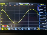
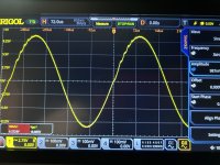
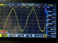
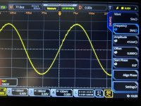
The positive cycle of the right channel shows some issues in the pics. It becomes just barely noticeable at 500 hz and 1 watt and gets worse as frequency and power increase. I’m using an 8 ohm load resistor. The amp sees about 12 ohms impedance on my crossovers.
The pics are at 1w 1khz, 1w 3khz, 5w 3khz and 5w 8khz. Not sure they are showing in order in the post but the parameters are visible on the right.
Is this what would be called ringing?
BTW, swapped mosfets between channels. Problem remained on right channel.
Attachments
Last edited:
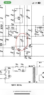
There is no typical miller cap but there is C9 between collector and ground. In the input stage frequency compensation is done with C3-R8 and C4-R18. Ensure they are proper value and cap type.
For output stage I would check C13 first, in the original manual it is 390pf but installed between Gate and Source of the mosfet. Gate and Drain cap would require much smaller value and indeed the type of cap used will make a difference there.
C6-R24 is a feedback frequency compensation.
Fab
For output stage I would check C13 first, in the original manual it is 390pf but installed between Gate and Source of the mosfet. Gate and Drain cap would require much smaller value and indeed the type of cap used will make a difference there.
C6-R24 is a feedback frequency compensation.
Fab
Last edited:
Thanks, all.
if the pics aren’t clear, the boards are PC-6.
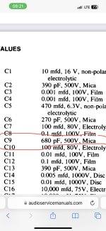
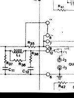
Fab, I don’t see C9 in a position as you describe. See schematic. As for C13, I did indeed change those to 33pf G-D and they are PP. Replacement ceramics have been ordered.
C18 has been changed from 680pf to .01mf per this thread, but I now see mica was original, and I goofed and went with PP again. If this matters I will order micas. I also did not replace either C19 as they tested good. Quite a bit of time soldering in the new wiring scheme direct to the fuses, so I will order new ones of those as well In case I cooked them.
I did not replace the original C3 or C4 as they tested good. I did replace all resistors, going a bit overboard with .1% plus matching even tighter when dealing with mirrored pairs like R8 and R18, as well as careful matching of all BJT pairs. I think the matching paid off as I have +59.85vdc and -59.87vdc, .6mv and .11mv dc offset, and very evenly matched bias at 275ma that slowly decreases to about 265 after warmup.
I don’t suppose Rick’s soft start on the right channel’s PSU filter cap would be a factor, would it? I can’t test that theory by just disconnecting it as the relay won’t close, and rewiring the mains at this point would be tedious. I think there are many of these out there and they work very well, and I haven’t heard of any complaints.
Jeff
if the pics aren’t clear, the boards are PC-6.
Fab, I don’t see C9 in a position as you describe. See schematic. As for C13, I did indeed change those to 33pf G-D and they are PP. Replacement ceramics have been ordered.
C18 has been changed from 680pf to .01mf per this thread, but I now see mica was original, and I goofed and went with PP again. If this matters I will order micas. I also did not replace either C19 as they tested good. Quite a bit of time soldering in the new wiring scheme direct to the fuses, so I will order new ones of those as well In case I cooked them.
I did not replace the original C3 or C4 as they tested good. I did replace all resistors, going a bit overboard with .1% plus matching even tighter when dealing with mirrored pairs like R8 and R18, as well as careful matching of all BJT pairs. I think the matching paid off as I have +59.85vdc and -59.87vdc, .6mv and .11mv dc offset, and very evenly matched bias at 275ma that slowly decreases to about 265 after warmup.
I don’t suppose Rick’s soft start on the right channel’s PSU filter cap would be a factor, would it? I can’t test that theory by just disconnecting it as the relay won’t close, and rewiring the mains at this point would be tedious. I think there are many of these out there and they work very well, and I haven’t heard of any complaints.
Jeff
Jeff
See C9 in the schematics with value also. There may be other schematics of DH-200 with different parts label.
If you have bypassed the output fuses then then C19 had no effect.
The question about soft start is in case the relay contacts are damaged and no not completely short the resistor. A possible consequence of the weak bass….The soft start is not mandatory but only in the long term so you can bypass it for test.
As for the VAS current you should have at least 1V across R27 and R33 emitter resistors.
Fab
Attachments
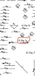
Thanks Fab. Yes I have that C9, I was thrown off by the “collector and ground” note as I don’t see that here. C9 is one of the components I did not change as it tested good.
I have not bypassed the speaker fuses, just bypassed the board loop by jumpering pins 8 and 11, and connecting pin 12 to the fuse, again per a suggestion here that made sense to me.
I have 1.11vdc on R33 and 1.06 on R27 right channel, and 1.10 and 1.09 respectively on left channel.
I have 0.0vdc across the resistor on the soft start with 18mv of 60hz. noise.
Again, I did not replace any BJTs. Perhaps I should rethink Q8 and Q13?
This from post #93:
1. Bypassed loop from circuit card eyelets 8 and 11 with a jumper. Then, speaker out (eyelet 12) was daisy chained through the speaker protection fuse to the red output terminals. Speaker ground or return (eyelet 6) went direct to the main ground between the two PS caps (known hereafter as G1). The black speaker terminals were also connected to G1.
Post 1109 makes the same suggestion with different pins because he was referring to a PC-19 board.
The fuse remains between output and speaker, but the R36, 37, 38 ,L1, C11 and 12 are bypassed.
Am I misreading this? Is it a bad idea that the suggesters just happened to not report back on? I can undo it, though it means a lot of disassembly and rewiring.
Post 1109 mentions 12 gauge wire not pin #12…not sure to properly interpret post #93….
Anyway, You cannot bypass R36, 37, 38 ,L1, C11 and 12 output filter since the amp may become instable….
you can bypass fuse F4 -to Rely on the other amps protections - but not the output filter.
Fab
Anyway, You cannot bypass R36, 37, 38 ,L1, C11 and 12 output filter since the amp may become instable….
you can bypass fuse F4 -to Rely on the other amps protections - but not the output filter.
Fab
Last edited:
and post 141:
2. Removed the wiring of the speaker fuse loop by jumpering
eyelets 6 and 8 together. Speaker output from eyelet 5 is now
daisy-chained through the back panel fuse and then to the red
speaker terminal. The black speaker terminal is attached to the
circuit ground between the two PS caps. Speaker ground output
from eyelet 7 now goes directly to main circuit ground.
Eyelet 5 on the PC-19 board is equivalent to eyelet 12 on the PC-6 board. All 3 of these posters appear to have bypassed the filter.
I am not being argumentative fab. I am forever grateful for your assistance. I’m already feeling guilty about having hijacked this thread even though it is long in the tooth, like me! If there is a better way to continue this, if no one else is benefitting, please tell me.
I was a bit hesitant to make any changes to the original circuit that didn’t have multiple endorsers. This one seemed to make sense, especially the grounding change. It can be undone.
Jeff
do not worry… there is no hijack here. This is a multi purpose thread even involving new design!
I have no problem with the grounding change but for the output filter removal I really really doubt anybody succeeded while keeping good stability performance with amp…😉
if you keep the same circuit as original designer (Erno Borbely who worked for Hafler) so the original DH-200, do not remove the output filter. This is a high feedback factor amplifier design so everything is important to keep proper stability. This filter has a purpose and is not optional. It was not put in to increase the parts count… you can maybe simplify it but not remove it. Some of my own amplifier designs do not have this filter but these are different topology with much much lower feedback factor design and else characteristics…
Fab
Last edited:
Fab,
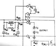
See attached. The zobel network is not bypassed by this mod. It simply moves the F4 fuse and C19 cap from between pins 8 and 11, to between pin 12 and J2 (speaker positive.) The jumper now between 8 and 11 keeps all original circuits in play. I don’t see how this could modify the signal path in a detrimental way.
See attached. The zobel network is not bypassed by this mod. It simply moves the F4 fuse and C19 cap from between pins 8 and 11, to between pin 12 and J2 (speaker positive.) The jumper now between 8 and 11 keeps all original circuits in play. I don’t see how this could modify the signal path in a detrimental way.
Attachments
Jeff
unfortunately the presented mod is somewhat worse than the original layout. In original layout the fuse internal resistance effective value is reduced by the feedback factor of the amp - because within the amplifier circuit. With the mod it is now outside of the feedback loop of the amp so a direct increase of amplifier output impedance thus reducing the damping factor…..the C19 parallel cap with fuse has no real bypass effect at audio frequency in the modded circuit.
If this effect is what you want then it is ok but it is not the usual way to increase output impedance ….
Fab
Last edited:
Well impedance matching theory is still a big mystery to me, so while I would have thought the fuse is acting like a dead short, I’ll defer to your judgement on this. I will return the circuit to its original design and report back. Thanks.
- Home
- Amplifiers
- Solid State
- Hafler DH-200/220 Mods