I might be too late, but have you considered using the vertical height of the cabinet for your port? I did that in one of my prototypes, and it worked great. I used 2- 4" diameter aluminum tubes for dual ports. The only issue with the design is the port exit has to make a 90 degree bend. I don't think it is a huge problem, but my quick and dirty solution needs refinement!
Mine speaker is different in that I am using a 10" driver, but total volume - port volume is ~100L. So roughly the same volume as what you are working with?
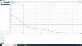
I also tried a single 4" diameter port, which was a lot shorter length...but I got bass compression and distortion! (3-5% distortion @20hz.) The design pictured has ~1% distortion down to 20hz. This measurement is with a steep 20hz high pass, and the mic is in front of the port, hence the bump in low frequency output. Without the high pass, it rolls off at 20hz.
(There is an issue at ~100hz, but I'm pretty sure that is my port exit design. That can be fixed...but instead I'm developing a different solution now.)


Mine speaker is different in that I am using a 10" driver, but total volume - port volume is ~100L. So roughly the same volume as what you are working with?
I also tried a single 4" diameter port, which was a lot shorter length...but I got bass compression and distortion! (3-5% distortion @20hz.) The design pictured has ~1% distortion down to 20hz. This measurement is with a steep 20hz high pass, and the mic is in front of the port, hence the bump in low frequency output. Without the high pass, it rolls off at 20hz.
(There is an issue at ~100hz, but I'm pretty sure that is my port exit design. That can be fixed...but instead I'm developing a different solution now.)
I would dispute the veracity of this comment! There ARE other solutions. Just need to be clever.Anything other than a single, round, flared and properly sized port is sub-optimal, will reduce output, and add distortion.
For example, Genelec's "laminar spiral enclosure" (LSE). The sub looks like a short barrel with square ends. They use a slot port that follows the radius of the cabinet, and they are extremely non-resonant. I had one some years ago, and it was really impressive! Mine was the 7060B, so it wasn't very big. But crazy good.
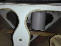
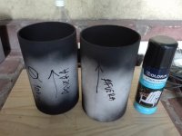
Then there is my dual port design that also measured pretty good. I would say it shows promise, but needs some tweaking in the implementation. (Photo in my previous post on this thread)
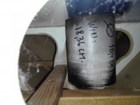
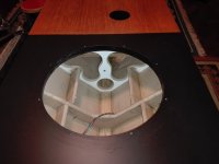
And then I did a hybrid version, combining the area of the dual ports into a radius like Genelec uses. I only just made it and installed it in a cabinet, so this is very preliminary. I considered a adding a turning vane to reduce turbulence, but that probably isn't necessary.
But I am quite pleased. Distortion is low, response is down to 20hz as intended. (Mic was placed in front of the port, explaining the peak...and the tiny dip at ~23hz is caused by the port vibrating...due to it not being securely mounted. It is a prototype. I only just stuck it in a cabinet yesterday! Also a 20hz high pass is in play in this measurement.)
Yes, and I abandoned the idea because any small object that was accidentally introduced would require a huge job to recover it. Also, WAF likes to put decorative gadgets on that surface.I might be too late, but have you considered using the vertical height of the cabinet for your port?
............................
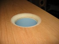
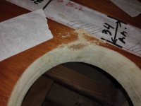
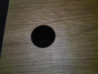
And yes, it is too late to modify that or any other location of the ventilation. It is already finished. My router is a hobby tool, nothing professional, so it doesn't go to the desired depth, and I had to complete the job by hand, but I had a little carelessness and it didn't come out "perfect". I am very detailed and I thought of solving it by applying a small chamfer as you can see in the photo.
According to Troels, it will not be significant in tuning.
http://www.troelsgravesen.dk/vent_tuning.htm
Attachments

I'm sorry, but the connection is very slow and I'm consuming a lot of bits to upload photos. A few days ago there was a tremendous electrical storm here, 😡 lightning damaged the modem and the provider company assigned me very few gigabytes (10) to be able to navigate using the smartphone as a router. They promised to change it in the next week.....🤐
Attachments
We will need a photo of th
I did consider venting mine out the top, but I had not thought about things falling into the sub. That would be annoying!Yes, and I abandoned the idea because any small object that was accidentally introduced would require a huge job to recover it. Also, WAF likes to put decorative gadgets on that surface.
And yes, it is too late to modify that or any other location of the ventilation. It is already finished. My router is a hobby tool, nothing professional, so it doesn't go to the desired depth, and I had to complete the job by hand, but I had a little carelessness and it didn't come out "perfect". I am very detailed and I thought of solving it by applying a small chamfer as you can see in the photo.
According to Troels, it will not be significant in tuning.
http://www.troelsgravesen.dk/vent_tuning.htm
The entry and exit profiles of the port must be as close to identical as possible, otherwise port rectification will push the cone away from its rest position.I am very detailed and I thought of solving it by applying a small chamfer as you can see in the photo.
For a standard port you have the tube with the hard edges on the inside and a flush mounted tube with a lot of boundary on the outside - so a massive difference in exit situation.
Do you have more detailed infos about this topic?
Do you have more detailed infos about this topic?
There is plenty of detailed information through Google.Do you have more detailed infos about this topic?
Oh yes, "tuning tube rectification", entire books written on that phenomenon, as with diodes...
This sounds interesting, it is about the group delay of the BRs, although it is commercial propaganda from a manufacturer about their own products, I liked reading this!
https://barefacedaudio.com/pages/how-ports-work
" 4. The reason ported cabs are deemed to have worse transient response than sealed cabs is because their transfer function is different. An 'ideal' ported cab has a 24dB/octave cut-off but an 'ideal' sealed cab has a 12dB/octave cut-off. The steeper cut-off rate causes the transient response to be less accurate - this can be proved mathematically and is true to all filters - the steeper the slope the greater rate of change of the phase shift and thus the greater the group delay.
However, an 'ideal' ported cab isn't actually ideal! The way our 12XN ported cabs are designed means that the LF roll-off is actually much closer to a 12dB/octave transfer function, which results in excellent transient response (in conjunction with the higher efficiency and power handling of a ported vs sealed cab). "
20 Hertz have a wavelength of 17 meters = 50 Ms
If Win Isd is correct with the calculations, the GD of this cabinet at 20 Hz is 12.4 Ms. 😎
Attachments
but I want to exit or excite at an odd harmonic interval (1/3 from a closed end) or I have other issues .. port shape and size is Bass reflex issues , but then this^^^ is the next one and even more important often ??? (I dunno ??)
I don't understand English, I'm sorry, thanks anyway, but do you think it's necessary for me to apply some of that to improve my cabinet ? And how would it be ? 😉
You should start with a premise: I have no intention of changing the box or the speaker.
You should start with a premise: I have no intention of changing the box or the speaker.
Other than the strong self centered bias, it's not wrong. Equal response = more or less equal GD and phase.although it is commercial propaganda from a manufacturer about their own products
The flare of one end can affect a little or a lot, but one thing is clear, the behavior of the tube will be as if we lengthened it, that is, tune FB lower. That would involve recalculations if I want to keep the exact tune chosen, ( 30 Hz, slightly above 28 Hz Fs) so I prefer to stick with my first choice.Yes, and I abandoned the idea because any small object that was accidentally introduced would require a huge job to recover it. Also, WAF likes to put decorative gadgets on that surface.
And yes, it is too late to modify that or any other location of the ventilation. It is already finished. My router is a hobby tool, nothing professional, so it doesn't go to the desired depth, and I had to complete the job by hand, but I had a little carelessness and it didn't come out "perfect". I am very detailed and I thought of solving it by applying a small chamfer as you can see in the photo.
According to Troels, it will not be significant in tuning.
http://www.troelsgravesen.dk/vent_tuning.htm
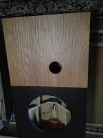
With a bit of sawdust mixed with vinyl glue (PVC) - made from the same veneer wood that I saved opportunely - I filled in the imperfection. When it is dry I will sand it and if necessary it will be touched up with the same varnish that I used originally.....
Attachments

Don't get too hung up on 'exact' tuning - the actual tuning frequency in operation is considerably altered by temperature and output level, and changes over time of Fs.
Yes, as neither the controller type will not change the FB, thanks to both . 👍
" Vent tuning is only related to the mass of the air in the box and vent and the dimension of the vent has nothing to do with the driver and in practical terms any driver can be used for these experiments, but don't use a tiny 4" driver for a 29.5 litre enclosure."
http://www.troelsgravesen.dk/vent_tuning.htm
Last edited:
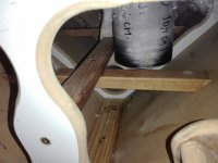
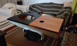
Ok, I'm near the end. I'm thinking that it would be interesting to place the speakers together and listen to a sealed cabinet and the one modified to BR to evaluate the sound of each one, but moving these guys is not easy so I think the BR will go directly to its corner. (no, it's not a penance, ha)
I have a question here:
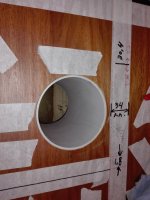
The cabinet has been completely emptied of the polifyll, but I plan to cover ONLY the bottom side walls with fiberglass, to prevent standing waves from bouncing off the speaker. Thoughts ?
I have a question here:
The cabinet has been completely emptied of the polifyll, but I plan to cover ONLY the bottom side walls with fiberglass, to prevent standing waves from bouncing off the speaker. Thoughts ?
Attachments
- Home
- Loudspeakers
- Subwoofers
- Sealed subwoofer to bass reflex, what do I gain and what do I lose ?