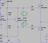
That sounds about right. If we also know the voltage across that 1k2 I circled we can get close to the correct value of single resistor needed in place of the multiplier.Brilliant 👍
That's up to you. 28C is nothing.
That sounds about right. If we also know the voltage across that 1k2 I circled we can get close to the correct value of single resistor needed in place of the multiplier.
I assume you are measuring this across the 1 ohm test resistor.
The buzzing could be a number of things, even using a bulb tester might do that as the supplies will fall a little and any regulated supplies might drop out of regulation. To trace it you need to use the scope. Look what the buzz actually is. 50Hz, 100Hz or something else? and also look at the rails.
It is +12.5v
Removing the drivers will cause the bias current increase massively so you need to be aware of that and get the multiplier to a state that won't allow that to happen.
Something like 2k as a total value for both resistors will be needed here. You can just remove both initially and that will give a low bias.

Something like 2k as a total value for both resistors will be needed here. You can just remove both initially and that will give a low bias.
this is where i currently have the pre set, so you just want me to take that out then and that is a 2k, so all i need to do for now is turn it right down
That sounds about right. If we also know the voltage across that 1k2 I circled we can get close to the correct value of single resistor needed in place of the multiplier.
It is +12.5v
We can use that information to calculate what will be a resistor to replace the multiplier.
12.5 volts across 1k2 is 10.4 milliamps. That current flows in the multiplier and the set resistors.
If you had 840 millivolts between the gates at your chosen bias current then the new resistor would be R=V/I which is 0.84/0.0104 giving 80.80 ohms
Does that work... yes it does 🙂 R643 is the new resistor and is 81 ohm and its not that critical.
this is where i currently have the pre set, so you just want me to take that out then and that is a 2k, so all i need to do for now is turn it right down
You need to be able to bring the voltage across the mutiplier down to below the 0.84 volts you measured earlier. The lower the voltage the lower the bias current.
The sim shows around 1k7 for 100ma current so in the real world that could be a bit higher (or lower). A 2k as a minimum value for preset sounds reasonable.
ok so that should be pretty straight foRward, but i dont have a non polarised 2.2uf cap
Electrolytic is fine (perfect). Just make sure polarity is correct. Anything over 6.3 volt rating is OK as it sees only a small voltage.
so like this thenYou need to be able to bring the voltage across the mutiplier down to below the 0.84 volts you measured earlier. The lower the voltage the lower the bias current.
The sim shows around 1k7 for 100ma current so in the real world that could be a bit higher (or lower). A 2k as a minimum value for preset sounds reasonable.
View attachment 1137503
Attachments
The other option 😀 plus at the top. Look at the multiplier. It is an NPN so the collector would be the most positive relative to the emitter.
Nothing bad would happen if it failed as it would just reduce the bias further.
Nothing bad would happen if it failed as it would just reduce the bias further.
so this is for friday then as there isnt enough time today to start this and im not rushing itso like this then
so for now i am listning to it as it is and it sounds great i have to say
again like the 3020, i have listened to dozens now, and it is def an improvement, quite a bit i would say from a 'treble' point
That's great to hear, as you know I'm a great fan of Lateral FET's and think they are brilliant for audio.
Excellent, well done 👍
Excellent, well done 👍
It is weird about the noise but you really have to do some scope work to get a clue what might be happening. I can't really second guess what might be going on there.
I see on the circuit there is a cap directly between what would have been the base's of the outputs. Is that present on what would now be the FET gates? or is it present but on the other side of the gate stopper resistors.
If it is across the gates directly that could be a problem.
I see on the circuit there is a cap directly between what would have been the base's of the outputs. Is that present on what would now be the FET gates? or is it present but on the other side of the gate stopper resistors.
If it is across the gates directly that could be a problem.
If the “buzz” has kind of a 60-Hz-ish sound to it don’t discount the possibility of a power supply issue. It might show up more with the LatFets which can operate higher in frequency than 3055’s. Could be rectifier noise, which is load (ie bias current) dependent. It might always have been there but now with the output transistor change, becomes audible.
Worth it though, has made a difference. Going to remove the drivers Friday so we can see it that improves it even moreToo bad they cost more than a 2N3055 and a driver, or NAD might have used them.
the cap is still there, and it will be across the bases as these positions have not changed like the other 2 connectionsIt is weird about the noise but you really have to do some scope work to get a clue what might be happening. I can't really second guess what might be going on there.
I see on the circuit there is a cap directly between what would have been the base's of the outputs. Is that present on what would now be the FET gates? or is it present but on the other side of the gate stopper resistors.
If it is across the gates directly that could be a problem.
- Home
- Amplifiers
- Solid State
- NAD 3130 conversion to Lateral FET