Here's why PSUD2 is so useful.
I am going to attach 4 images.
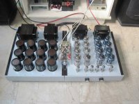
They show a power supply I am using for a 45 amp with Ale's gyrators. My choke and transformer are Antek and the shown resistance values are as measured. The exact details don't really matter, and in any case, I tweaked the final current draw (the 76mA to 84mA shown) for a small test. Forgot to revert that for these screenshots!
The point of all this is to show what you can learn from PSUD2. I am not an expert and this is just based on my experience in building and optimizing two different SET amplifier circuits (one SS, one 5U4GB). All of my interpretations of PSUD2 output are based on my reading DHT Rob's guide:
https://www.dhtrob.com/overige/pdf/dhtrob_psu.pdf
The curves in the images below are the voltage starting at 0 seconds at capacitors C2 and C3. I show:
Because of my low transformer secondary impedance, a circuit using SS rectification without any added series resistance is not sufficiently damped. You can see this as the "hump" in the voltage plot. This is not something you want.

So I added 60 Ohms in series before C1 and you can see what happens. That initial surge is damped.

Just for illustration, I switched the SS diodes out for a 5U4G rectifier. This is with no other changes. I don't endorse this circuit but did it just for illustration! The ramp up time for the power supply is much more drawn out.

And, finally, a 5AR4. The voltage drop is less AND the ramp up time for the PSU is much reduced.

Personally, I'm really interested in this discussion since I have always wondered what differences would be audible, if any, between a power supply which showed the exact same behavior in PSUD2 but were not the same in construction.
So, for example, a SS rectified PSU that, when you compared the first 1.5s of behavior with a 5U4G rectified supply, looked more or less the same in PSUD2.
This may be hard to accomplish and would require some very different component values (chokes, transformers, resistors, capacitors all would be different, I expect).
Hope this has been informative. If you could get this working on your computer, you could say, "I like the sound of an insufficiently damped power supply." There are some, for example, that prefer AC heated DHT filaments. Some would say that they like the IMD that results from this approach. There is also an approach to power supplies which stresses that the series resistance of the PSU must be as low as possible. The counter-argument to this approach is that what you likely end up with is a bunch of "noise" in your PSU due to under damping.
Also, you may enjoy this builder's explanation of "time constants" and their role in designing PSUs:
http://a-direct-heating-triode.blogspot.com/2018/06/lcr-phono-preamp-part-3.html
I am going to attach 4 images.
They show a power supply I am using for a 45 amp with Ale's gyrators. My choke and transformer are Antek and the shown resistance values are as measured. The exact details don't really matter, and in any case, I tweaked the final current draw (the 76mA to 84mA shown) for a small test. Forgot to revert that for these screenshots!
The point of all this is to show what you can learn from PSUD2. I am not an expert and this is just based on my experience in building and optimizing two different SET amplifier circuits (one SS, one 5U4GB). All of my interpretations of PSUD2 output are based on my reading DHT Rob's guide:
https://www.dhtrob.com/overige/pdf/dhtrob_psu.pdf
The curves in the images below are the voltage starting at 0 seconds at capacitors C2 and C3. I show:
- Undamped SS rectification
- Damped SS rectification
- 5U4G
- 5AR4
Because of my low transformer secondary impedance, a circuit using SS rectification without any added series resistance is not sufficiently damped. You can see this as the "hump" in the voltage plot. This is not something you want.
So I added 60 Ohms in series before C1 and you can see what happens. That initial surge is damped.
Just for illustration, I switched the SS diodes out for a 5U4G rectifier. This is with no other changes. I don't endorse this circuit but did it just for illustration! The ramp up time for the power supply is much more drawn out.
And, finally, a 5AR4. The voltage drop is less AND the ramp up time for the PSU is much reduced.
Personally, I'm really interested in this discussion since I have always wondered what differences would be audible, if any, between a power supply which showed the exact same behavior in PSUD2 but were not the same in construction.
So, for example, a SS rectified PSU that, when you compared the first 1.5s of behavior with a 5U4G rectified supply, looked more or less the same in PSUD2.
This may be hard to accomplish and would require some very different component values (chokes, transformers, resistors, capacitors all would be different, I expect).
Hope this has been informative. If you could get this working on your computer, you could say, "I like the sound of an insufficiently damped power supply." There are some, for example, that prefer AC heated DHT filaments. Some would say that they like the IMD that results from this approach. There is also an approach to power supplies which stresses that the series resistance of the PSU must be as low as possible. The counter-argument to this approach is that what you likely end up with is a bunch of "noise" in your PSU due to under damping.
Also, you may enjoy this builder's explanation of "time constants" and their role in designing PSUs:
http://a-direct-heating-triode.blogspot.com/2018/06/lcr-phono-preamp-part-3.html

One thing I learned with PSUD2 is that you cannot use SS diodes in choke input supply. The initial voltage spike will destroy diodes with even the highest voltage rating. It is either tube rectifier, or some kind of varistor protection. I use varistors even with tubes.
One thing I learned with PSUD2 is that you cannot use SS diodes in choke input supply. The initial voltage spike will destroy diodes with even the highest voltage rating. It is either tube rectifier, or some kind of varistor protection. I use varistors even with tubes.>>
Thanks for that. How did you learn this? What diodes failed and what were their voltage rating?
Since 6A3sUMMER uses a diode bridge with choke input since 1996, one would think they worked in his case?
Thanks for that. How did you learn this? What diodes failed and what were their voltage rating?
Since 6A3sUMMER uses a diode bridge with choke input since 1996, one would think they worked in his case?
I also use SS diodes and choke input power supplies...never had a problem but the diodes need to be rated high...as a rule of thumb I use 2.5 times the secondary voltage (which is good practice regardless).
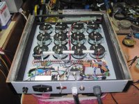
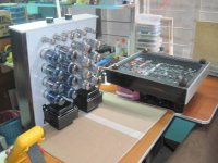
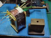
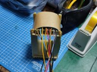
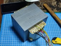
Andy, here is the B+ in the power supply chassis of one of my monobloc multichannel amplifiers:

The Black Art stuff are low DCR elements, oversized cores with minimal temperature gain in use. Tried snubbers but they really had little work to do thanks to those diodes plus they but did raise the impedance of the power supplies which for this build was certainly a no no.
The Black Art stuff are low DCR elements, oversized cores with minimal temperature gain in use. Tried snubbers but they really had little work to do thanks to those diodes plus they but did raise the impedance of the power supplies which for this build was certainly a no no.
One thing I learned with PSUD2 is that you cannot use SS diodes in choke input supply. The initial voltage spike will destroy diodes with even the highest voltage rating. It is either tube rectifier, or some kind of varistor protection. I use varistors even with tubes.
No problems at all on my choke input power supply. Two 1N4007 diodes in series and I’m pretty sure psud2 didn’t warn me.
Never solid state... for the sake of the tubes plus solid state will carry a bunch of crap into the amp and tube will not. Built over 1500 tube amps all with tube rectifiers.
DHT especially, why use solid state there it just makes it sound so sterile. If you want dynamics put a good high transconductance in front of the DHT.
Gordon
DHT especially, why use solid state there it just makes it sound so sterile. If you want dynamics put a good high transconductance in front of the DHT.
Gordon
More so in supplies with multiple LC stages and minimal DCR. The possibility of supply ringing increases dramatically. A damper diode's low dynamic impedance relative to standard rectifier tubes can exasperate this.Here's why PSUD2 is so useful.
Never solid state... for the sake of the tubes plus solid state will carry a bunch of crap into the amp and tube will not.
Gordon
Define “crap”.
Never solid state... for the sake of the tubes plus solid state will carry a bunch of crap into the amp and tube will not. Built over 1500 tube amps all with tube rectifiers.
DHT especially, why use solid state there it just makes it sound so sterile. If you want dynamics put a good high transconductance in front of the DHT.
Gordon
i used a 16A 1000V flatpack bridge rectifier on my 16KT88 triode mode amplifier, the owner was so ecstatic!!!, what tube rectifiers can you use for that?
Attachments
-
 993461_647911221897182_2077737866_n.jpg77.9 KB · Views: 132
 -
 563120_647914005230237_1870723617_n (2).jpg119.6 KB · Views: 133
 -
 541477_647910628563908_1461128631_n (2).jpg104.7 KB · Views: 126
 -
 1012477_647913521896952_173951551_n (2).jpg109.2 KB · Views: 132
 -
 1235540_647909921897312_1620020605_n (2).jpg74.6 KB · Views: 133
Might have to upgrade to one of these bad boys. https://www.lighting-gallery.net/gallery/displayimage.php?album=2837&pos=56&pid=183540
Liquid /vapor state. Much like (my) promised weather tomorrow. Winters were easier in Pa. Well, sometimes.
All good fortune,
Chris
All good fortune,
Chris
Use a solid state rectifier and a choke input filter. It is OK.
Caution: follow the rules
1. Measure the un-loaded secondary voltage of your tube amplifier power transformer . . . when your power mains are their highest voltage (time of day, season, these things are turned of in your house (water heater, stove, dryer, electric heater, etc.).
2. Multiply the measured unloaded secondary rms voltage by 1.414, that is the maximum peak voltage to the rectifiers, when the output tubes are cold.
3. Multiply that voltage by 2 (you have to remember, an un-loaded input choke supply is not 0.9 x, it is 1.414 times the un-loaded rms volts, so the capacitor after the choke is now at 1.414 the un-loaded rms volts.
Simply put, the reverse volts across the 'off' diode, is 1.414 x 2 x unloaded rms volts.
Example:
A 325V-0-325Vrms secondary might measure 350V-0-350Vrms when it is un-loaded, with the power mains at its maximum voltage (time and seasonal).
350Vrms is about 500V peak.
When the power supply is un-loaded (cold output tubes), the peak reverse volts across the 'off' diode is 1000 Volts (500V from the secondary, and 500V in the reverse direction from the capacitor; while the voltage across the 'on' diode is 0.6 to 1.0V.
In this case, use a diode that has a reverse voltage rating of 1500V, even better if it is rated 2000 volts or better.
Use a protected multi-outlet power strip.
Just my opinions.
Your Mileage May Vary
As 6A3sUMMER says, just be conservative. Semi-con rectifiers can be series'd, with voltage dividing resistors. Watch the resistors' voltage ratings; 150K Ohm 2W carbon comp is a pretty safe choice across a 600 PIV Hexfred. I've used 4 series'd in each leg of a FW bridge to make nominal 1170 VDC, LCLC, in service since 1995 without drama. At voltages high enough to really challenge capacitor voltage ratings, some effort to time delay the power to the high voltage transformer needs to come into the plan too.
All good fortune,
Chris
All good fortune,
Chris
from what i understood, the spec, 350V-0-350Vrms is the voltage when the rated dc milliamperes flow thru a resistor load, correct me if i am wrong.....so that that 350vac can be higher when read unloaded...
350-0-350 is 700vrams total so 2.1kv peak, and this is the piv value of any ss rectifier to use..
since i make my own power traffos to use in my tube amps, i have forsaken the use of center tapped hv traffos, a single 350vac secondary will work fine even if you use tube rectifiers, this is with the aid of some silicon rectifers...http://www.valvewizard.co.uk/bridge.html
the full wave voltage doublers are even better, used in the Harman Kardon Citation II and Pioner, Sansui Japanese amps followed too...https://www.ampslab.com/SCHEMATICS/LowRes/HarmonKardonCitation2.jpg
the use of the lower voltage of 350vac in the case of the hybrid rectifiers and an even lower voltage in the case of full wave voltage doublers make winding traffos safer, faster and best of all, more economical....
i made a power traffo with the 240vac primary as the highest voltage, followed by the 190vac secondary@2A good for 500+vdc rails...ohis ine has three screens, between primary and core, after the primary winding and after the main secondary windings.....
Attachments
Last edited:
For the first iteration of my first from-scratch amplifier, I used a CLCLC arrangement that I more or less pulled out of a hat. Initial C was tiny (to cut the voltage), then got bigger as you went on (and bigger was always better). That sort of basic thinking. It sounded pretty bad, as many of you have no doubt already assumed! When deep bass came up in a song, the sound it produced was not unlike that of a car dragging a loose muffler down the street.More so in supplies with multiple LC stages and minimal DCR. The possibility of supply ringing increases dramatically. A damper diode's low dynamic impedance relative to standard rectifier tubes can exasperate this.
PSUD2 helped me come up with something structured and logical. It also allowed me to do that with the components I had on hand. Eventually I abandoned LCLC altogether because it was just so difficult to do right.
One other way I've used it: after straightening out my power supply, I tweaked the decoupling cells for the input stages in the amp as well. (The schematic I was using was the JE Labs 2A3 Deluxe). For example, I went from 20uF decoupling caps to to 1uF, using the basic method I showed above, and found the effect to be what I expected: faster, controlled recovery behavior led to a better-sounding input stage with no meaningful loss of PSRR (this was so late in the chain that this was effectively no longer needed).
The tube b+ is lower and will sag a lot more under load. The silicon diode adds 100mv to the sag after its .7v drop.
There will be a audible difference when the b+ can move 50v when compared to silicon.
There will be a audible difference when the b+ can move 50v when compared to silicon.
class A amps like the single ended triodes are fixed type loads, once the tube are warmed up there is no more sag to worry about...
Class AB is different, here the sag comes into play from idle to full power...
Class AB is different, here the sag comes into play from idle to full power...
- Home
- Amplifiers
- Tubes / Valves
- Solid state versus tube rectifiers in a PSU