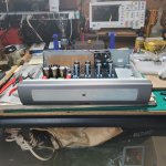
After all the consideration, found one on ebay that fits the build. I found a smaller profile chassis that houses the unit perfectly, but I'll probably need to separate the power supply housing from the pre-amp. Question for those that went this route (independent power chassis/mono block), how would you go about wiring a second switch for the main board? (standby switch) I found this nifty halo led ring-type switch, that will probably be used as the "standby" switch that will power the unit. The main power switch will be in another chassis with power transformer and choke housed inside.
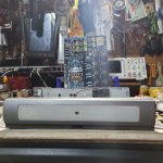
Here's the chassis I found at local thrift shop ( I'll have to ditch the exposed tube idea). Have some ideas to modify it a little. ( VU meter, power switch, lights, vinyl or tolex wrap)
Attachments


How about having the heaters on once the Main power switch is on, and the HV supply via the standby switch at the main housing?After all the consideration, found one on ebay that fits the build. I found a smaller profile chassis that houses the unit perfectly, but I'll probably need to separate the power supply housing from the pre-amp. Question for those that went this route (independent power chassis/mono block), how would you go about wiring a second switch for the main board? (standby switch) I found this nifty halo led ring-type switch, that will probably be used as the "standby" switch that will power the unit. The main power switch will be in another chassis with power transformer and choke housed inside.
Perfect, just wanted to confirm which one should be with main on and which should be stand by. Just to be sure I don't short or surge anything, would it be alright if one of the 250v goes to switch, while the other 250-0 connects directly to board? Cutting the supply voltage of HV in half? If I'm not mistaken, that's how most standby operates?
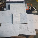
I have made my own chassisDimensions are in .dxf file attached. Not with every detail drawn, just coarse drawing
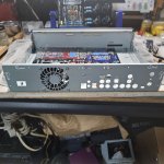
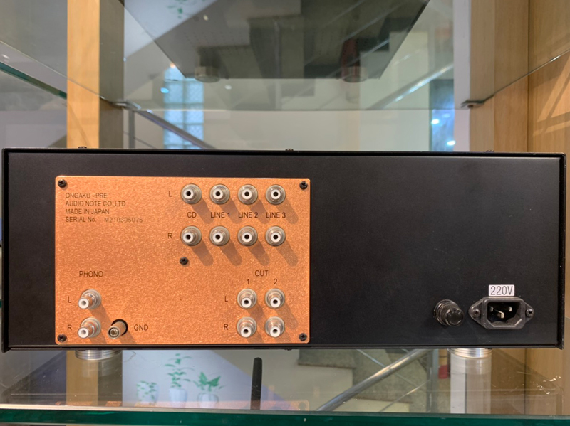
Just out of curiosity what are these additional rca jacks for?
heh, nvm just realized they could be the phone out-put. Does anyone use them if, when using the main output? Or perhaps speaker jacks for some small bookshelf speakers?
Looping at enaB's pictures, me thinks he has two outputs per side, maybe for biamping or a subwoofer. Simply parallel?
I opened up my M77 and took some photos of the balance pot. This allows for at least some attenuation. Bear in mind that I have no idea if this actually is the proper way to wire this.Noticed most shorted their balanced pot, I have an MN-taper pot with a center click, was there anything special you did to make it work? If convenient, any close-up pics of how you wired this?


Another output connectors in parallel 🙂 I'm not sure what their purpose is, but original design has them, so I put them too 🙂
A scope manufacturer put a piece of metal in one of their scopes.
Another scope manufacturer put the same piece of metal in their scope, a good copy of the original scope.
The reason for the piece of metal? It had no purpose other than to prove that a patent had been infringed on by the second manufacturer.
Always copy a design, without knowing why.
Another scope manufacturer put the same piece of metal in their scope, a good copy of the original scope.
The reason for the piece of metal? It had no purpose other than to prove that a patent had been infringed on by the second manufacturer.
Always copy a design, without knowing why.
Thanks! I've read somewhere, they mentioned balance are great for whenever one tube degrades more than the other. Interesting wiring on the switch... I would have totally got that wrong. I just shorted it like everyone else. Didn't feel like put another pot knob through the case, lol.I opened up my M77 and took some photos of the balance pot. This allows for at least some attenuation. Bear in mind that I have no idea if this actually is the proper way to wire this.
View attachment 1136314View attachment 1136313
Thanks for pointing to the right direction, after closely following the diagram and references to other site, I wired the "Stand-by" switch to the first 2k resistor before the cap. Added in a resistor and cap to prevent arching. Sharing in case someone else is interested, or care to correct me. I'm enjoying all this.........(until something smokes,lol)How about having the heaters on once the Main power switch is on, and the HV supply via the standby switch at the main housing?
I'm the third guy, infringing on everyone's infringement. 😅😃A scope manufacturer put a piece of metal in one of their scopes.
Another scope manufacturer put the same piece of metal in their scope, a good copy of the original scope.
The reason for the piece of metal? It had no purpose other than to prove that a patent had been infringed on by the second manufacturer.
Always copy a design, without knowing why.
If you are a commercial business, infringing on another commercial business, or on a properly patented circuit,
Then guess who gets Rich . . .
The Lawyers
Then guess who gets Rich . . .
The Lawyers
Aaaahhhhh, i knew it! Those actually can come in very handy for all kinds of reasons..... 😀Another output connectors in parallel 🙂 I'm not sure what their purpose is, but original design has them, so I put them too 🙂
yes. or for your favourite headphone amp , or for biamping,, or........
I even added symmetrical outputs to connect to my next speaker build.
I even added symmetrical outputs to connect to my next speaker build.
An idea which would most folks here would be a list of modifications which could be applied to the KSL-M77 all in one place. It would be fantastic to be able to go shopping on the list which would be ordered from most to least important.
Example - I had never heard of the 33K-50K resistor mod. I wonder what other juicy mods are available that I missed? I did add a choke to the standard B+ power supply location.
Another example would be replacing the pot next to the rectifier with a 14V zener? Isn't
14V a little hot for 12.6V filaments?
But I am here to tell you that for the relative few mods I have in mine, my KSL-M77 sounds pretty awesome!
And yes, the GE JG-6072s made quite the difference! Even if the were $50/ea...
Thanks
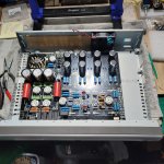
I couldn't agree more, the amount of preparation and double-checking everything (added my own mod along the way). Read and re-read everyone's post frequently. I think this group was able to create a much more improved product than it was originally designed.
Attachments
If I wanted to add in a Bluetooth module, would you guys suggest adding it to this unit or to the PA?
- Home
- Amplifiers
- Tubes / Valves
- Kondo KSL-M77 phono preamp clone project