Thanks. I have no problem using stepped or tapered segments in HR - the problem that both Brian Steele and Lord Sansui have talked about is that the exactly geometry of each turn must be precise. Otherwise, why use the Excel sheet to calculate this?
If I'm wrong, I'll just use manual calculations for the CSA at each turn.
If I'm wrong, I'll just use manual calculations for the CSA at each turn.
Is there anything I can do that might help you build that version in your software?
Hello joetekubi,
The software isn't mine, it's opensource initiative that me and other take advantage, I just make a tool on top of this software.
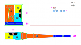
Here are two models.
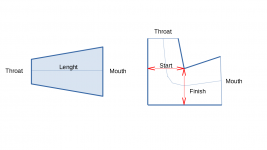
MLTL4 - Has the panels as you asked but as you will see the segment H1 and H2 can't be flared.
MLTL5 - To flare H1 and H2 , it was needed to add two more panels witch create some empty volume inside the box. You have one flare control for H1+H2 and a second flare control for H3.
You can compare both in terms of performance and see what you like most. Let me know this was what you were looking for.
regards
Attachments
What's the issue? Use the stepped function in HR.
Fortunately there was no need to use stepped function for this case as you can see in the post #102
I don't trust too much on sketches that are not made from CAD software, I just get the idea from them.
Yeah, but you still have wasted space.
Where did you post how to import HR txt files into FreeCAD? I spent hours yesterday looking for it and trying to input the individual fields into Excel window.
If I can't EASILY import the HR files into the program, then FreeCAD is worthless to me. I'm fine with 2D Excel.
Where did you post how to import HR txt files into FreeCAD? I spent hours yesterday looking for it and trying to input the individual fields into Excel window.
If I can't EASILY import the HR files into the program, then FreeCAD is worthless to me. I'm fine with 2D Excel.
Where did you post how to import HR txt files into FreeCAD? I spent hours yesterday looking for it and trying to input the individual fields into Excel window.
If I can't EASILY import the HR files into the program, then FreeCAD is worthless to me. I'm fine with 2D Excel.
Hello BP1Fanatic,
The workflow fron FreeCAD and Boxplan is the same, from the box to hornresp. Unfortunately, inverting the workflow from Hornresp to FreeCAD or boxplan brings a lot of issues.
The difference between FreeCAD to Boxplan area:
- You have more design options, see the link https://freeloudspeakerplan.rf.gd/pages/boxplan.htm
- it's faster to implement new design
- You have up to 5 levels of automation with Hornresp, so if you know what you are doing you can fine tune in a minute see link https://freeloudspeakerplan.rf.gd/pages/automation.htm
- You have a full 3D model, multi-body, and you can generate the 2D for each panel, you can check many information inside the box to confirm dimensions, accessibility, handling, wheels, and others. Boxplan has no CAD, it's just a sketch drafter.
- You can export the 3D to other software like Google Sketchup and others to check integration with architecture, check the look with other boxes and so on.
- The box is ready to build, you just need to add braces, wheel and any other feature you want.
If FreeCAD tool is worthless for you it's fine. The important point here is to offer options to people and each one according to their individual preferences will use the tool they like most. Boxplan is amazing as FreeCAD, they offer different advantages and different ways to interface with, that's fine too.
I do not use any boxplans. I freehand in Excel with my HR models.
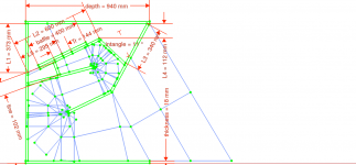
Nice, it's very challenging to fold a flared horn, this is where the CAD really shiny and just few people can guarantee a price progression and automated process during this folds. The major part of CAD I saw the folded values were manually defined, so it will work just for that particular design, if you change one dimension the model will not work anymore, or to work it will requires you to manually adjust the folds again. To avoid this behavior, with FreeCAD I fully automated the process so you can modify the box to fit a 8" driver or 21". See attachment #1
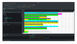
While using FreeCAD, in the spreadsheet part the cells are colored, the ones indicated in green user should not change them unless you want to customize your file, they are automatically calculated from an expression. Just the yellow ones the user needs to input a value like the box width, drivers assembly hole, and driver T/S parameters, there is a legend there. See attachment #2
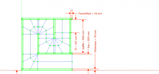
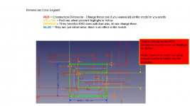
The most important inputs come from the sketch dimensions colored in RED as you can see in the attachment #2 from the TL1 design as an example. See attachment #3
Attachments

Thanks for the models - they look close to what I need.Hello joetekubi,
The software isn't mine, it's opensource initiative that me and other take advantage, I just make a tool on top of this software.
Here are two models.
MLTL4 - Has the panels as you asked but as you will see the segment H1 and H2 can't be flared.
MLTL5 - To flare H1 and H2 , it was needed to add two more panels witch create some empty volume inside the box. You have one flare control for H1+H2 and a second flare control for H3.
You can compare both in terms of performance and see what you like most. Let me know this was what you were looking for.
regards
I installed Freecad, loaded your data files, but all I see in Freecad is a baffle with a circular opening.
I tried running the macros, but nothing happened.
I don't want to derail this thread with Freecad tutorial, but unable to experience your models.
Hello joetekubi,
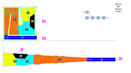
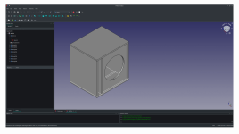
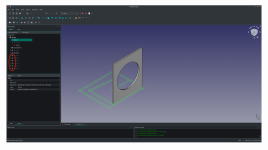
When opening the 3D model (*.FCStd) for the first time you should see them as indicated in the attachment #1 taking MTL4 version as example.
Sometimes, people type in the keyboard without noticing or click here and there trying to learn the program witch can creating some issues. From what you describe, it looks like some panels was hidden, this happen if you select a body and press "SPACE", when an element is colored in the three view it will be displayed, if its gray its hidden (not displayed) see attachment #2, please, check if this is your case.
I'm using FreeCAD versions 0.20.2 check if you are using the most updated version available.
Attachments
OK, I had to jump though some hoops to install freecad --edge, which gives me version .21
now the Model in MLTL5 loads ok.

now the Model in MLTL5 loads ok.
Hello,
New plans released as indicated below:
New plans released as indicated below:
- Altec816-2
- Altec817-1
- Altec817-2
- MLTL4
- MT
- Manifold-1-Dual
- Manifold-2
- Manifold-2-Dual
- Manifold-3-Dual
- Altec-816 renamed to Altec-816-1
- Manifold-MTB renamed to Maifold-1
- some small fixes
To clarify, you have to change the red lines (redlining🤔) in order for the green Excel cells to populate correctly?Nice, it's very challenging to fold a flared horn, this is where the CAD really shiny and just few people can guarantee a price progression and automated process during this folds. The major part of CAD I saw the folded values were manually defined, so it will work just for that particular design, if you change one dimension the model will not work anymore, or to work it will requires you to manually adjust the folds again. To avoid this behavior, with FreeCAD I fully automated the process so you can modify the box to fit a 8" driver or 21". See attachment #1
While using FreeCAD, in the spreadsheet part the cells are colored, the ones indicated in green user should not change them unless you want to customize your file, they are automatically calculated from an expression. Just the yellow ones the user needs to input a value like the box width, drivers assembly hole, and driver T/S parameters, there is a legend there. See attachment #2
The most important inputs come from the sketch dimensions colored in RED as you can see in the attachment #2 from the TL1 design as an example. See attachment #3
To clarify, you have to change the red lines (redlining🤔) in order for the green Excel cells to populate correctly?
Yes
The "redlining" are the constrains that define dimensions, the bluelining are just information and the orange ones are linked or they have expressions inside them.
You can find the list of inputs for each model opened the picture provided in the zip file called MODELNAME-inputs.png
The third place you could check the inputs are in the spreadsheet in the group called Sketch input value.
So in summary, if you open the sketch, and double click in a redlining dimensions and change the value the magic will happen, everything will be updated automatically for you 🙂
Macro is the next magic.
Attachments

Last edited:
Hello,
New plans released as indicated below:
https://freeloudspeakerplan.rf.gd/
New plans released as indicated below:
- Paraflex R Dual
- TL3
- TL1 - Updated in order to add more segments (H3 and H4) and allow more design flexibility
- TL2 - Updated in order to add more segments (H3 and H4) and allow more design flexibility
- Boxplan availability updated to align with currently models available
https://freeloudspeakerplan.rf.gd/
Hello,
New plans released as indicated below:
https://freeloudspeakerplan.rf.gd/
New plans released as indicated below:
- Infrabass-Dual
- LabHorn-Dual
- Posh-2
- SmallHorn-1
- SmallHorn-1-Dual
- SmallHorn-2
- SmallHorn-2-Dual
- K-bin
- K-bin - Dual
- X-sub
- Posh renamed to POSH-1
- Boxplan availability updated to align with currently models available, format changed to better aligned with menu categories and order.
https://freeloudspeakerplan.rf.gd/
I'm thinking about creating a video tutorial about how to use the models, so people can see they working and what they offer.
Just to use the model you don't need to know much about CAD, while building your own model or changing existing is a different history.
Just to use the model you don't need to know much about CAD, while building your own model or changing existing is a different history.
Hello,
New plans released as indicated below:
https://freeloudspeakerplan.rf.gd/
New plans released as indicated below:
- TQWT-2
- TQWT renamed to TQWT-1 and upated to align with TQWT-2.
- Automation removed from menu.
- How to use it removed from menu.
- Tutorial added to menu with 12 videos to better illustrate how to use the models and macros.
- Adding soft color to menu to better see the groups
https://freeloudspeakerplan.rf.gd/
that's insane!!!
Crazy!!
Great tutorials !!!
Thanks for making those.
Crazy!!
Great tutorials !!!
Thanks for making those.
- Home
- Loudspeakers
- Subwoofers
- Find here Parametric CAD files for loudspeakers plan - Hornresp integrated