The super scoop 2 looks interesting to try and adapt to the dimensions in the sim I have been looking at. Would it be involve much modification to have the mouth facing the rear so it could make use of 1/2 pi radiation?The basshorn also is worth a look if modified to have it act as a backloaded horn wththe driver located differently.
Attachments
Would it be involve much modification to have the mouth facing the rear so it could make use of 1/2 pi radiation?The basshorn also is worth a look if modified to have it act as a backloaded horn wththe driver located differently.
CAD is a nice tool and for me it's very fast to release new layout, sometimes I evaluate new layout but they don't became a full model because the results are not interesting. See the attached evaluation for instance. The models X4b and X5b are interesting I may keep working on them in a future.
If you have an idea in mind, try to make a sketch using image editor or powerpoint and post here so I can try to create at least and sketch model for you to run simulations in a easy way, if it work well I could finish all 3D model.
If it's for home use you may find the models TQWT interesting and easier to build check videos below. They are full range in those cases but it don't need to be.
Attachments

The mouth to that design could easily be located on the front, side, or rear of the enclosure. The same thing can be done to any TL or TH type designs.
Hi, really great work!!
Freecad is crashing on me relentlessly and is most frustrating, any chance you could roll out some of these layouts into other free tools such as fusion 360?
Secondly while I think I kind of understand the advanced centerline methodology it appears what I draw is in absolute conflict when converting this information into cad designs. Right off the bat converting from a dual sub enclosure to half or a single enclosure the line length shifts technically speaking.
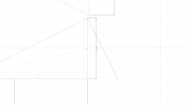
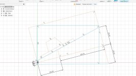
A simple example would be S1 value 1000, L12 30cm & S3 being 5000 with L23 being 60cm on a simple dual enclosure making S2 2289, now halving the enclosure halves the above values but the center line also changes in both length and position. I have attached an image which shows half the original enclosure S1 being 500 in this example S1 is 10cmx50cm but with the new angle which is or should represent the 50cm, I would perceive the new angle should be 50cm ( 55.902) is the length of the new angle?
Secondly S3 is it projected against the dashed line or the original line to 50cm, again I would assume to the dashed line vs the original dual loaded enclosure being the 3rd reference image.
Many thanks in advance
Freecad is crashing on me relentlessly and is most frustrating, any chance you could roll out some of these layouts into other free tools such as fusion 360?
Secondly while I think I kind of understand the advanced centerline methodology it appears what I draw is in absolute conflict when converting this information into cad designs. Right off the bat converting from a dual sub enclosure to half or a single enclosure the line length shifts technically speaking.
A simple example would be S1 value 1000, L12 30cm & S3 being 5000 with L23 being 60cm on a simple dual enclosure making S2 2289, now halving the enclosure halves the above values but the center line also changes in both length and position. I have attached an image which shows half the original enclosure S1 being 500 in this example S1 is 10cmx50cm but with the new angle which is or should represent the 50cm, I would perceive the new angle should be 50cm ( 55.902) is the length of the new angle?
Secondly S3 is it projected against the dashed line or the original line to 50cm, again I would assume to the dashed line vs the original dual loaded enclosure being the 3rd reference image.
Many thanks in advance
Attachments

Thank you.Hi, really great work!!
Freecad is crashing on me relentlessly and is most frustrating, any chance you could roll out some of these layouts into other free tools such as fusion 360?
FreeCAD was the best option I found for free and cross-platform offering as many feature as we need. Did you tried to update to the latest version? or you can even try it in a virtual machine.
A simple example would be S1 value 1000, L12 30cm & S3 being 5000 with L23 being 60cm on a simple dual enclosure making S2 2289, now halving the enclosure halves the above values but the center line also changes in both length and position.
There is one small issue in your advanced centerline, you need to make the middle line orthogonal as you can see in the attachment.
There will be Horn length different between single box design compared to dual one.
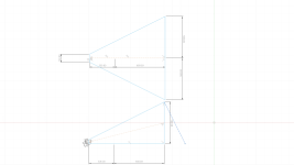
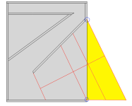
In general the single driver box will present little longer horn length because the mouth is "incomplete". Take a look in the attachment#2, if you consider (blue circles) the upper corner of the mouth the horn is longer, if you consider the lower corner, the horn is shorter, so this is the reason I'm calling the mouth incomplete, the yellow area does not exit in the box in terms of panels to restrict the sound waves. So, if you sit the box in the ground, the floor might work as and extension making the mouth more complete, so the pioneer guys of box design, while cross checking data to compare model with real world saw this behavior like the horn length ending outside the box. While for subwoofer it might be fully trustful, maybe for top box there could be some small differences once there might no be the ground effect, considering this case I took the conservative side of thinks and simulate with middle ground length between upper and lower corners, safer place.
Dual driver horn design has complete mouth, as you already demonstrate in your pictures, so, even if it might be shorter, the driver will couple and improve the low end frequencies response.
Having two single boxes or dual box might be tricky and we need to think about advantages/disadvantages of them, maybe they are not exactly the same in terms of response but they will not be the same in terms of material needed to build them. There will always be a trade-off in same way or another.
Attachments
Hi Sansui & thank you kindly for the response!
It appears the folding and unfolding of horns are completely eluding me however I am tenacious on getting this right, so in advance thank you for the patience and the time on the subject.
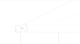
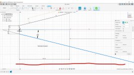
From my primitive example attached I need to orientate the base and the rear to 90 degree or orthogonal as you mentioned.
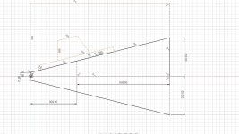
So If I understand correctly I'm rotating this whole horn by I think in this instance by around 14 degree +- to have the bottom of the horn flat on the floor like image 2 & keeping to a traditional box shape would look like image 3 (dotted lines is the change angle) thus keeping the center of the horn line 90 degree from to back?
Which makes great sense if this is the correct method to look at the horn, it would also explain why I have some small difference in segment volumes!!
It appears the folding and unfolding of horns are completely eluding me however I am tenacious on getting this right, so in advance thank you for the patience and the time on the subject.
From my primitive example attached I need to orientate the base and the rear to 90 degree or orthogonal as you mentioned.
So If I understand correctly I'm rotating this whole horn by I think in this instance by around 14 degree +- to have the bottom of the horn flat on the floor like image 2 & keeping to a traditional box shape would look like image 3 (dotted lines is the change angle) thus keeping the center of the horn line 90 degree from to back?
Which makes great sense if this is the correct method to look at the horn, it would also explain why I have some small difference in segment volumes!!
Attachments
Hi Sansui & thank you kindly for the response!
It appears the folding and unfolding of horns are completely eluding me however I am tenacious on getting this right, so in advance thank you for the patience and the time on the subject.
From my primitive example attached I need to orientate the base and the rear to 90 degree or orthogonal as you mentioned.
So If I understand correctly I'm rotating this whole horn by I think in this instance by around 14 degree +- to have the bottom of the horn flat on the floor like image 2 & keeping to a traditional box shape would look like image 3 (dotted lines is the change angle) thus keeping the center of the horn line 90 degree from to back?
Welcome.
The image 3 looks like correctly representing that horn path. Remember to consider it as Parabolic Flare inside Hornresp.
Hello, post the plan here and I can work and try to implement it. 👍
Olá Lord! Obrigadão pelo teu trabalho irmão 🙂
Estou à procura de algum plano para sub 18", possivelmente horn. Encontrei os planos para construir um Hog Scoop mas preciso de ajuda para calcular a resposta no Hornresp. Já tens modelos de freecad para este sub (http://hornplans.free.fr/hogscoop.html) ? Ou para outros para 18" que recomendes? Também estou a ver se consigo alterar um dos outros planos de 15" para 18", mas ainda não percebo como mudar as medidas do cabinet...
Obrigada
Google translate seems close enough?
Hello Lord! Thanks for your work brother 🙂
I'm looking for some plans for sub 18", possibly horn. I found the plans to build a Hog Scoop but I need help calculating the answer in Hornresp. You already have freecad models for this sub (http://hornplans.free. fr/hogscoop.html) ? Or for others for 18" that you recommend? I'm also seeing if I can change one of the other plans from 15" to 18", but I still don't understand how to change the cabinet measurements...
Thanks
These shapes don’t seem to help anything in the low freq response if I take that whole box volume and just make it a ‘normal’ rectangle attached to the same port??CAD is a nice tool and for me it's very fast to release new layout, sometimes I evaluate new layout but they don't became a full model because the results are not interesting. See the attached evaluation for instance. The models X4b and X5b are interesting I may keep working on them in a future.
If you have an idea in mind, try to make a sketch using image editor or powerpoint and post here so I can try to create at least and sketch model for you to run simulations in a easy way, if it work well I could finish all 3D model.
If it's for home use you may find the models TQWT interesting and easier to build check videos below. They are full range in those cases but it don't need to be.
Voight pipe was pre simulation and understanding of qw by us ‘mere mortals’ maybe ? It’s not of much use it seems (just an observation) ?
Well, the 'real' Voigt designs were/are well understood by 'those practiced in the art' (gotta love patent 'speak! 😉), but IIRC these popular DIY designs were based on Ralph West's 1949 Decca Corner Horn article that David Weems 'aped' much later to a much wider audience.

Olá Lord! Obrigadão pelo teu trabalho irmão 🙂
Estou à procura de algum plano para sub 18", possivelmente horn. Encontrei os planos para construir um Hog Scoop mas preciso de ajuda para calcular a resposta no Hornresp. Já tens modelos de freecad para este sub (http://hornplans.free.fr/hogscoop.html) ? Ou para outros para 18" que recomendes? Também estou a ver se consigo alterar um dos outros planos de 15" para 18", mas ainda não percebo como mudar as medidas do cabinet...
Obrigada
Olá Chiarini,
No site existe um seção de tutorial com vários vídeos explicando como usar o modelo e como alterar as medidas. Usar um projeto existente de alguém é uma opção se o altofalante que deseja usar possui características T/S parecidas, caso contrário é melhor ajustar o modelo para o seu altofalante. É bem fácil de usar o modelo Freecad, a inteção foi deixar de forma que qualquer pessoa pudesse alterá-lo. Caso precise de ajuda posso ajudá-la também. Quanto a uma sugestão de modelo de 18" ou 15" para indicar vai depender um pouco daquilo que você procura, em geral os objetivos envolvem:
Tamanho da caixa (L)
Largura da banda (Hz)
Nível de Pressão Sonora (SPL)
Atenciosamente,
https://freeloudspeakerplan.rf.gd/pages/tutorial.htm
Obs.: uma vez que estamos num forum internacional eles pedem que postemos em inglês, poderemos usar português em mensagens particulares pela caixa de mensagens.
Hello Chiarini,
There is a tutorial section in the website with some videos explaining how to use the model and how to change dimensions. Use any design made from someone is an option if the driver you want to use has similar T/S characteristics, otherwise is better to adjust the model for your driver. It's very easy to use the Freecad model, the intention was to let the model in a way that everyone could change it. In case you need help I can help you too. Regarding suggestion for 18" or 15" models, it will depend from what you are looking for, what are your targets:
Size (L)
Bandwidth (Hz)
Sound PRessure Level (SPL)
Regards,
Note: Once we are at global forum they asked us to post using English, we can use Portuguese from private message using the inbox.
These shapes don’t seem to help anything in the low freq response if I take that whole box volume and just make it a ‘normal’ rectangle attached to the same port??
In general restriction the air flow helps to improve low end and to reduce group delay.
The model is flexible enough for you to compare constant cross session vs tapered one.
@Booger weldz
Yeah, there's been several iterations over the decades; there's a really interesting folded tapered console that memory fails me now........in the meantime, Hegeman's multi resonant pipe sub.
Yeah, there's been several iterations over the decades; there's a really interesting folded tapered console that memory fails me now........in the meantime, Hegeman's multi resonant pipe sub.
Dead link lost in the new forum app ? 😥@Booger weldz
Yeah, there's been several iterations over the decades; there's a really interesting folded tapered console that memory fails me now........in the meantime, Hegeman's multi resonant pipe sub.
Attachments


whatare they referring to (half wave in a quarter wave pipe? just a frequency that isnt out of phase with the front of the driver, unlike the full wave length freq(4/4)?
- Home
- Loudspeakers
- Subwoofers
- Find here Parametric CAD files for loudspeakers plan - Hornresp integrated