So folks, if i get it right, let me sum it up:
-By reducing gain (in either stages) will help increase headroom?
-And to achieve that, i can either lower value of the drain resistors and/or increase value of the source resistors?
-Also, the second stage is prone to clipping first because it has to deal with the amplified signal from the input stage?
R5 is essentially R1 in the Lipshitz transform, but SY called it "the build out resistor" in his "His Master's Noise" article.- R5 is more than a build out resistor. It is the series element in the RIAA EQ network. Its value has a large influence on the shape of the output curve in the lower frequencies.
I dropped the OP's circuit from post #1 into LTspice and gave it a spin.
I don't have a SPICE model for 2SK170BL, so I substituted LSK170B. I couldn't get the simulation to run with the higher Idss LSK170C.
The M44-7 cartridge has a nominal rated output at 1kHz (10cm/dyne) of 9.5mV (0.0095V). Tracking a +20dB peak, that would be 95mV (0.095V). That completely crunches the 2nd stage. The problem seems to be that in the circuit from post #1, the voltage at Q2's source is less than 200mV, but the signal level there with a 95mV input is about 400mV. Crunch.
I raised the B+ to +36V, and started increasing resistor values to get more headroom. That raised the drain voltages on Q1 to 28V and Q2 to 29V. The source voltages became 218mV for Q1 and 245mV for Q2. With 95mV input, the 1kHz signal level at the gate of Q2 was 225mV.

That succeeded in getting rid of the early clipping, but the gain dropped by quite a bit, and the EQ now rolls off the bass more. If I increase the value of R5 to 27k, the bass gets closer to flat, but now the gain goes down again.
Also, the THD is still pretty high.
With 9.5mV 1kHz sine wave at the input, the output was 355mV peak and THD was 0.17% (H2 -55dB). Gain at 1kHz is only 31.5dB.
With 95mV 1kHz sine wave at the input, the output was 3.39V peak and THD was 1.86%.
I'm giving up. I'm not sure a Le Pacific is a good choice for a high output DJ cart like the M44-7. I'm not sure it's a good choice for anything, but I don't know for sure, as I've never built one, and I've never heard one.
For an M44-7, I'd use a couple of opamps or 6DJ8 tubes, especially since the input capacitance of the JFET is going to be high anyway, so tubes would work as well, but with much higher headroom.
I'm sure someone else can do a better job of optimizing this circuit for the M44-7.
I don't have a SPICE model for 2SK170BL, so I substituted LSK170B. I couldn't get the simulation to run with the higher Idss LSK170C.
The M44-7 cartridge has a nominal rated output at 1kHz (10cm/dyne) of 9.5mV (0.0095V). Tracking a +20dB peak, that would be 95mV (0.095V). That completely crunches the 2nd stage. The problem seems to be that in the circuit from post #1, the voltage at Q2's source is less than 200mV, but the signal level there with a 95mV input is about 400mV. Crunch.
I raised the B+ to +36V, and started increasing resistor values to get more headroom. That raised the drain voltages on Q1 to 28V and Q2 to 29V. The source voltages became 218mV for Q1 and 245mV for Q2. With 95mV input, the 1kHz signal level at the gate of Q2 was 225mV.
That succeeded in getting rid of the early clipping, but the gain dropped by quite a bit, and the EQ now rolls off the bass more. If I increase the value of R5 to 27k, the bass gets closer to flat, but now the gain goes down again.
Also, the THD is still pretty high.
With 9.5mV 1kHz sine wave at the input, the output was 355mV peak and THD was 0.17% (H2 -55dB). Gain at 1kHz is only 31.5dB.
With 95mV 1kHz sine wave at the input, the output was 3.39V peak and THD was 1.86%.
I'm giving up. I'm not sure a Le Pacific is a good choice for a high output DJ cart like the M44-7. I'm not sure it's a good choice for anything, but I don't know for sure, as I've never built one, and I've never heard one.
For an M44-7, I'd use a couple of opamps or 6DJ8 tubes, especially since the input capacitance of the JFET is going to be high anyway, so tubes would work as well, but with much higher headroom.
I'm sure someone else can do a better job of optimizing this circuit for the M44-7.

No way... 🙂 I hope you also know what a VDS higher than 7v does to a jfet noise...to roll off bass you can use a low value input coupling capacitor like 1...10nF
Last edited:
Ah, I see. The original Le Pacific used no source resistors at all, on either of the two JFETs. That allows use of the JFETs with Vds of only about 5V, but there is not nearly enough headroom to pass a 100mV signal without significant clipping, so not a good match for any DJ carts.
It looks like people have been worrying this basic circuit for a long time: http://www.klaus-boening.de/le pacific.htm
Have a look at Salas' Simplistic nJFET RIAA.
With a DJ cart producing 9.5mV at 10cm/dyne, you don't need much gain. 30dB gain at 1kHz will give 300mV out with 9.6mV in, and on +20dB peaks that will hit 3V output, which is all you need. One could easily get that much gain with the necessary EQ from a single good quality opamp, or from a 6DJ8 twin triode. I think either of those strategies would be a better fit for a high output DJ cartridge.
Last edited:
I have built a similar phono amplifier (https://www.andiha.no/audio/projects/phono.html) for my relative low output Ortofon pickup. It sounds very good and I have not noticed any high distortion or overload. The power supply is 24 V, and I have used 2SK170V (Relative high IDSS).
Various posts seem to confuse the thread owner.
Let's go back to the question in the first post.
First measure the drain voltages of the two FETs.
JFETs are highly variable devices, so primitive circuits such as this may require initial Idss screening or individual tuning.
In this circuit, the drain voltage of FET must be about half of the power supply voltage (about 9V).
Since the bottom part of the waveform is clipping, perhaps the drain of Q2 is at a lower voltage than that?
In that case, increase the source resistance so that the drain voltage becomes about 9V.It will probably be between 68Ω and 120Ω.
For the passive CR-RIAA type, the headroom of the first stage is also important, so please adjust the source resistance in the same way.
This will reduce the gain but increase headroom that may be fine and even desirable in your use case.
The above is based on the assumption that 2SK170 is genuine and the rank is BL.
Last edited:
Thanks everyone for your valuable inputs.
I am back at the bench and first thing was to take a peek at the transistors.
From what I gather their looks are ..not that promising.
Here you can see number is 1 (not I) and cutout at the top is sideways.
Plus the 7 is straight, not curved.


Probably not the right stuff..*
Next thing is to do some measurements and come back to you with some figures.
Will also try your suggestions:
-increasing supply V+
-lowering drain resistor value while increasing source resistor at 2nd stage (and possibly 1st stage too, just to be safe)
But, with possibly fake parts i might need to looking for some genuine Toshiba or Linear reissues asap!
Your thoughts?
*While googling for pics, I came upon a picture claiming the ones with this kind of lettering and non-centered cutouts are supposedly made in Malaysia instead of Japan.
Go figure..
.jpg")

I am back at the bench and first thing was to take a peek at the transistors.
From what I gather their looks are ..not that promising.
Here you can see number is 1 (not I) and cutout at the top is sideways.
Plus the 7 is straight, not curved.
Probably not the right stuff..*
Next thing is to do some measurements and come back to you with some figures.
Will also try your suggestions:
-increasing supply V+
-lowering drain resistor value while increasing source resistor at 2nd stage (and possibly 1st stage too, just to be safe)
But, with possibly fake parts i might need to looking for some genuine Toshiba or Linear reissues asap!
Your thoughts?
*While googling for pics, I came upon a picture claiming the ones with this kind of lettering and non-centered cutouts are supposedly made in Malaysia instead of Japan.
Go figure..
Last edited:
Thanks everyone for your valuable inputs.
I am back at the bench and first thing was to take a peek at the transistors.
Keen to hear how you get on.
From what I gather their looks are ..not that promising.
Here you can see number is 1 (not I) and cutout at the top is sideways.
Plus the 7 is straight, not curved.
View attachment 1128361
Those are definitely fakes. Once I bought the same Transistors (off eBay) and tried to use them for Pacific phono. This fake devices are JFETs, well sorted for IDSS, but with lower transconductance compared to genuine 2sk170.
There is a rule of thumb for 2sk170 found on eBay: if the sellers name is NOT punkydawgs then you won't get genuine Toshiba 2sk170. Second rule of thumb is: if they are offered cheap you also will receive fakes.
I suggest you to get the real deal 2sk170 BL, after that it makes sense to experiment with rail voltage and source resistors.
Genuine 2SK170B will have transconductance 22 to 30+ mS. Digikey carries the TI JFE150 which has gm of 18mS. They also carry the LinearSystems LSK170B which has gm of 22mS. The latter is available in a TO92 package.
In rough terms, gain = R(drain)/[Rsource + 1/gm] so you aren't terribly penalized by using either of the newer devices from TI or LinearSystems. Just make sure to set R(drain) such that the drain voltage is roughly half the supply voltage.
In rough terms, gain = R(drain)/[Rsource + 1/gm] so you aren't terribly penalized by using either of the newer devices from TI or LinearSystems. Just make sure to set R(drain) such that the drain voltage is roughly half the supply voltage.
But, with possibly fake parts i might need to looking for some genuine Toshiba or Linear reissues asap!
Your thoughts?
If your FET is fake, it will have a larger source resistance to make the drain voltage around Vcc/2. And the gain will be very small. In that case, getting a genuine Toshiba 2SK170BL or Linear's LSK170B is very much the right thing to do.
But this is how I think. It takes time and money to get new ones. they are very expensive. 🤔
Those fakes must have been re-marking of many cheap FETs on the market.
If those are ONSEMI's J112, Gm = 10mS (@Id = 2.7mA) can be obtained.
Therefore, connect an ele-cap of 220uF or more in parallel with the source resistor.
Since Gv ≒ R(drain)*Gm, about 30dB gain can be obtained per stage.
Try this on the first stage, and if it's still not enough, do the same on the second stage too.
If it still doesn't work, I will give up and move on to the right path.😆
Last edited:
Hello jackinnj
Normally, the phono amplifier for MM has a gain of about 40dB.
An output of about 30mV for a 1mV input (gain of about 30dB) in Stage 1 would be correct.
It is then attenuated by about 20dB in a passive RIAA network (@1kHz).
It would be reasonable to amplify by 30dB again in stage 2, so that the gain is about 40dB.
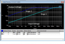
But your data shows 1V at the output of stage 2 at 1mV input. That's a gain of 60dB. This is comparable for MC.
What kind of circuit did your measurement data measure?Normally, the phono amplifier for MM has a gain of about 40dB.
An output of about 30mV for a 1mV input (gain of about 30dB) in Stage 1 would be correct.
It is then attenuated by about 20dB in a passive RIAA network (@1kHz).
It would be reasonable to amplify by 30dB again in stage 2, so that the gain is about 40dB.
But your data shows 1V at the output of stage 2 at 1mV input. That's a gain of 60dB. This is comparable for MC.
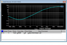
This is the OP circuit without the passive RIAA network, to illustrate gain compression.What kind of circuit did your measurement data measure?
Folks, sorry I didn't come back with some kind of update.
I was pretty busy these days.
But, I found some time tonight and applied the suggestions you so kindly proposed and the overloading problem has subsided!
In particular, I applied the following:
Regarding the second stage, I used 68Ω as source resistor (R12 on the schematic) and 2200Ω as drain resistor (R11 on the schematic).
Also, supply voltage was increased to 26VDC (in place of 18.6VDC on the schematic).
Now both parts of the sound-wave (top and bottom) remain clipping-free:

Before applying the changes, the sound-wave looked like this:

Also, I measured the following:
Voltage drop across R12 was around 300mV.
At the junction of R11 with the drain pin, voltage was around 15.5VDC.
So thanks again all of you guys.
Next thing, I'll probably need to get my hands on some genuine 2SK170BL..
I was pretty busy these days.
But, I found some time tonight and applied the suggestions you so kindly proposed and the overloading problem has subsided!
In particular, I applied the following:
Regarding the second stage, I used 68Ω as source resistor (R12 on the schematic) and 2200Ω as drain resistor (R11 on the schematic).
Also, supply voltage was increased to 26VDC (in place of 18.6VDC on the schematic).
Now both parts of the sound-wave (top and bottom) remain clipping-free:
Before applying the changes, the sound-wave looked like this:
Also, I measured the following:
Voltage drop across R12 was around 300mV.
At the junction of R11 with the drain pin, voltage was around 15.5VDC.
So thanks again all of you guys.
Next thing, I'll probably need to get my hands on some genuine 2SK170BL..
I have to regretfully report that (and with all due respects) there is no configuration of LePacific which will prevent clipping with the high output cartridge.
There is a way to configure the output stage with a PMOS FET, a la Pearl 2. See that thread for details.
There is a way to configure the output stage with a PMOS FET, a la Pearl 2. See that thread for details.
- Home
- Source & Line
- Analogue Source
- 2SK170 phono pre (Le Pacific) gets overloaded