It is correct that the output impedance increases with the value of R3, but I don't think it will increase that much to affect R5 so much.
Any decent RIAA circuit requires at least 1% resistors, including especially R5.

Agree, output impedance is mostly set by R4 so I'd leave R5 as is till I have the gain right.It is correct that the output impedance increases with the value of R3, but I don't think it will increase that much to affect R5 so much.
I will do a closeup, as well as DC measurement across the R3/R12. Problem is i am away for a few days.@evonimos I have built several iterations of this circuit. It's possible to make it work with high output MMs like the M44-7. There are old threads where others discussed this matter:
Please take a close up picture of your 2sk170 as there are lots of fakes on the market.
By the way, i too had a suspiscion that those might be fakes..
Agree, output impedance is mostly set by R4 so I'd leave R5 as is till I have the gain right.
Of course the proper R5 value depends on R3 and R4 ( and not the reverse ).
The R5 value must be determined with those values fixed.
The input stage DC bias must be correct, before addressing the RIAA and R5 value.
Last edited:
Of course there is also a thread about fake or real 2sk170:
https://www.diyaudio.com/community/threads/replacement-for-toshiba-2sk170-2sj74.317563/post-5732286
.jpg")
Once I had fakes bought from eBay, their top seam was not in the middle but on the side of the top. All fakes have way to low gain factor. That would be the most obvious reason for your problems with overloaded gain stages.
https://www.diyaudio.com/community/threads/replacement-for-toshiba-2sk170-2sj74.317563/post-5732286
Once I had fakes bought from eBay, their top seam was not in the middle but on the side of the top. All fakes have way to low gain factor. That would be the most obvious reason for your problems with overloaded gain stages.
I am a little confused to be honest.
My understanding regarding J-Fet bias and how it affects headroom is very limited!
I'll probably start by increasing R3 (and maybe R12) to 100R or so, also increase supply VDC a little.
And take it from there.
If i see improvement, i'll be in the right path.
Regarding the authenticity of the J-Fet parts, i will show you pictures when i am back.
But the problem with these parts is that i can't source them anymore. Maybe the Linear reissues from the DIay store but since i am in the EU and import taxes apply.
If all fails, i might try Crystal Fet v2 by RJM.
A similar circuit which employs the J113 instead. They're still available through Mouser.
The thread I shared before discusses a lot of those headroom an gain issues. I had the same questions like you a few years ago and Salas answered most of them in this thread. Might be a good read if you are away from your bench anyway..
Your problem gets tackled easily this way:
1.Use 2sk117(higher ds voltage, lower transconductance, twice the noise of 2sk170, much easier to source from old fostex cassette multitrackers for example or any fostex tape machine...fostex used them a lot, like my 8A R2R which has no less than 88 of them).
2.Use higher source resistor for bias to handle the higher input.Higher drain resistor too to keep the same gain.
3.Use an online passive riaa calculator of which many are available for a higher impedance network able to deal with the lower transconductance.
Ex:
https://www.kabusa.com/riaa.htm
http://www.klaus-boening.de/new phono stage lab page.htm
Last edited:
I have been playing with LTSpice for this circuit, assuming an IDSS = 8 mA, and my findings are:
With IDSS = 8 mA, Id = 3.4 mA for R3 = 47 ohms. With an input voltage of 50 mV peak at 1-3 kHz, the second stage clips. It helps to increase the supply voltage to 24 V. It also helps to increase R3 and R12 to for example 100 ohms.
With IDSS = 8 mA, Id = 3.4 mA for R3 = 47 ohms. With an input voltage of 50 mV peak at 1-3 kHz, the second stage clips. It helps to increase the supply voltage to 24 V. It also helps to increase R3 and R12 to for example 100 ohms.
By changing the values of r4 and r11, there will be no problem when you provide the supply voltage / 2 at the end of the jfets. In order to get the best efficiency, I recommend you to make your supply voltage 24v first.
my application is as follows and I am very satisfied

my application is as follows and I am very satisfied
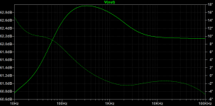
You are right.The RIAA network values result in a bulge in response in the deep bass area:
Intention was to 'cure' the original brightness and maybe provide a bit more 'body' and 'weight'.
Agree, as drawn the circuit has too much gain. Even with a standard 4mv output cartridge you would be lucky to avoid clipping. No chance with the high output Sure. To use with the M44 gain needs to be around 30dB. Simple maths nothing to do with fake devices. If you up the voltage be aware the resistor to the LED will need increasing.I have been playing with LTSpice for this circuit, assuming an IDSS = 8 mA, and my findings are:
With IDSS = 8 mA, Id = 3.4 mA for R3 = 47 ohms. With an input voltage of 50 mV peak at 1-3 kHz, the second stage clips. It helps to increase the supply voltage to 24 V. It also helps to increase R3 and R12 to for example 100 ohms.
Last edited:
Good for you, I always was bad at mathematics. Maybe that's why my first thought was about faked FETs (very common issue with 2sk170).Simple maths nothing to do with fake devices.
Sadly a problem with many components since the mid 2000's. Fake components that is 🙂Good for you, I always was bad at mathematics. Maybe that's why my first thought was about faked FETs (very common issue with 2sk170).
Last edited:
Yes, 'totally analogue' mate.
As you said.
High-output cartridges like Shure M44-7 or Pickering NP/AC (both nominally around 10mV), are better suited to gains of no more than 30-32dB.
Higher gains might overload either the RIAA stage itself, or other stages down the line.
Especially with 45rpm records or 33rpm that are cut rather hot.
For instance, i had to deal with clipping when connecting USB interfaces to digitize certain 'hot' vinyl records played with Shure M44-7 or Pickering NP/AC (or any pickups with nominal outputs above 5mV).
Right now, i am using a tube RIAA (L3 phono v2, by Audio Note) with the first stage unbypassed and B+ slightly lowered, to help reduce gain a bit. Had no problems with overloading on that.
But i really like a solid state, low power phono pre like this one. It doesn't consume much electricity and sounds really good when i'm using it with lower output cartridges like my Pickering TMZ22E.
Last edited:
R5 is the "build-out" resistor, but the output impedance at D1 must be factored into its calculation. A close approximation is the value of R4.
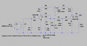
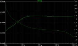
Here are some values which will get a more flat response curve.
If 60dB is too much gain, lower the drain resistor values of the JFETs. Increasing the source resistors will add to noise.
Here are some values which will get a more flat response curve.
If 60dB is too much gain, lower the drain resistor values of the JFETs. Increasing the source resistors will add to noise.
Attachments
I did some simulations and indeed it overloads above 10mV in the deep bass region.
Will breadboard next wk when back in NJ -- I do like the idea of keeping the first gain section as is.
For those who will try an SMD JFET device with adapter , Texas Instruments JFE2140 is SOIC-8 and available from DK. It tests exactly to the TI datasheet in terms of gfs and noise.
Will breadboard next wk when back in NJ -- I do like the idea of keeping the first gain section as is.
For those who will try an SMD JFET device with adapter , Texas Instruments JFE2140 is SOIC-8 and available from DK. It tests exactly to the TI datasheet in terms of gfs and noise.
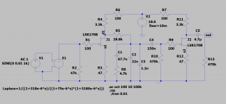
If you are using a high output cartridge, you can get output without clipping when you increase the value of R9 as seen in the simulation picture below.

It seems to me...
This suggests that one could increase the headroom of the second stage to avoid early clipping due to a hot signal coming from the output of the first stage+EQ.
- Yes increasing the value of the source resistor R12 would increase noise, but with the hotter signal from the M44-7 cart the noise will be similar to what it would have been using a cartridge with lower output. Hotter signal = less noise, but earlier clipping. Everything is a compromise.
- R5 is more than a build out resistor. It is the series element in the RIAA EQ network. Its value has a large influence on the shape of the output curve in the lower frequencies.
- If you reduce the value of R4 from 2.4k to 2.2k or maybe 2k, you will reduce the gain from Q1. However, you will have then decreased the Zout from Q1, requiring adjustment of the value of R9. BUT... There is a bass boost in there now, due to a larger than normal value for R9.
Lowering the Zout of Q1 relative to the value of R5 will decrease bass output a bit. Perhaps that will make the bass EQ flatter, plus reduce the gain a bit, making for a good compromise for use with the M44-7.
Everything is a compromise.
Perhaps also raise the value of R3 and R12 -- just a little -- to reduce gain, but not so much as to make increased noise a problem. Perhaps 62 or 68 ohms?
I haven't SPICE'd it yet, but perhaps a combination of the following will solve the problem:
Rather than hope for one change in part value to transform the whole circuit, make incremental changes throughout to optimize the circuit for your intended use. Maybe... Just a suggestion.
- The second stage will clip before the first stage.
- The second stage does not drive any part of the EQ network.
This suggests that one could increase the headroom of the second stage to avoid early clipping due to a hot signal coming from the output of the first stage+EQ.
- Yes increasing the value of the source resistor R12 would increase noise, but with the hotter signal from the M44-7 cart the noise will be similar to what it would have been using a cartridge with lower output. Hotter signal = less noise, but earlier clipping. Everything is a compromise.
- R5 is more than a build out resistor. It is the series element in the RIAA EQ network. Its value has a large influence on the shape of the output curve in the lower frequencies.
- If you reduce the value of R4 from 2.4k to 2.2k or maybe 2k, you will reduce the gain from Q1. However, you will have then decreased the Zout from Q1, requiring adjustment of the value of R9. BUT... There is a bass boost in there now, due to a larger than normal value for R9.
Lowering the Zout of Q1 relative to the value of R5 will decrease bass output a bit. Perhaps that will make the bass EQ flatter, plus reduce the gain a bit, making for a good compromise for use with the M44-7.
Everything is a compromise.
Perhaps also raise the value of R3 and R12 -- just a little -- to reduce gain, but not so much as to make increased noise a problem. Perhaps 62 or 68 ohms?
I haven't SPICE'd it yet, but perhaps a combination of the following will solve the problem:
- Some combination of a lower value of R4 and a higher value of R3 to reduce gain of Q1.
- Some combination of a lower value of R11 and higher value of R12 to reduce gain of Q2.
- Adjustment of the value of R9 may (or may not) be necessary to keep the desired bass EQ.
- Increase value of gate stopper resistor R9 to smooth out clipping behavior of Q2. Would 1k ohms be too much?
Rather than hope for one change in part value to transform the whole circuit, make incremental changes throughout to optimize the circuit for your intended use. Maybe... Just a suggestion.
- Home
- Source & Line
- Analogue Source
- 2SK170 phono pre (Le Pacific) gets overloaded