If the dip is required to be at a specific frequency simply set S2 to Auto in the Loudspeaker Wizard and adjust the L12 slider as necessary while observing the Output 1 response. Only the position of the driver will change, the overall length and profile of the horn will remain the same.So for non cylindrical profile the 1/4 WL we can use just as a raw approximation.
Attachments

Last edited:
Cool feature, it saves a lot of time not requiring to back to CAD. We are always learning Hornresp things.
Looks like he lost a lot of SPL in the upper range. To avoid increasing too much the L12, in this real case, I would rather "offset" horn flare, like increasing S1/S2/S3 until being able to assembly the driver. Is it possible to this in hornresp too? like setting S2 and S3 in auto, and keeping the same length, so if S1 is changed the other areas would adjust automatically in order to keep the same flare? see attachment illustration.
Looks like he lost a lot of SPL in the upper range. To avoid increasing too much the L12, in this real case, I would rather "offset" horn flare, like increasing S1/S2/S3 until being able to assembly the driver. Is it possible to this in hornresp too? like setting S2 and S3 in auto, and keeping the same length, so if S1 is changed the other areas would adjust automatically in order to keep the same flare? see attachment illustration.
Attachments
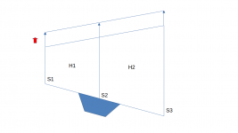
I would rather "offset" horn flare, like increasing S1/S2/S3 until being able to assembly the driver. Is it possible to this in hornresp too? like setting S2 and S3 in auto, and keeping the same length, so if S1 is changed the other areas would adjust automatically in order to keep the same flare?
It's not possible, and unfortunately the feature would require far too much work to implement at this stage. There could also be issues on how best to define "same flare", and whether it should apply to the radius profile or the area profile. Either way, it's not going to happen 🙂.
No worries, we have more then we are able to use. It's very fast to do that in the cad.
Thank you David and have a good weekend.
Thank you David and have a good weekend.
Very fast cuse you are a CAD ninja, but for us mere mortals that is next to impossible.No worries, we have more then we are able to use. It's very fast to do that in the cad.
Thank you David and have a good weekend.
for us mere mortals that is next to impossible.
If the horn is parabolic then the cross-sectional area will vary linearly with axial length, making it relatively easy to specify an increase in horn size while maintaining the same area expansion rate. For a two-segment parabolic horn with Auto S2, if S1 is increased by an amount S then all that needs to be done is to increase S3 by S also.
That is:
S1new = S1old + S
S3new = S3old + S
For example:
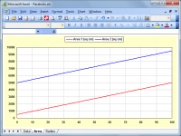
Given S1 = 500, S2 = Auto, S3 = 5000, L12 (Par) = 30 and L23 (Par) = 70, if S1 is increased to 5000 then S = 4500 and S3 needs to be increased to 9500 (5000 + 4500) to maintain the same area expansion rate, as shown in Attachment 1.
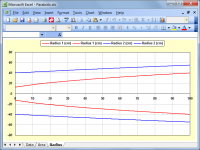
Note however that the axisymmetric profile of the parabolic horn changes even though the area expansion stays the same, as shown in Attachment 2. This is why I included the "same flare" comment in Post #13,303.
Attachments

Dear David, in the latest version, it seems I sometimes loose settings made in MEH Wizard. I noticed that with EQ and bandpass filters. I tweak the settings, press Save and when I open the wizard again, it loads the old settings. Is that intended behavior? If I press Save and then move one record back and forth and confirm to save before opening the wizard again, the settings will load correctly. I have not experimented much with the wizard before, so I am not sure if it behaved always like that.
Where are the EQ and bandpass settings stored? In the main record or ME1/2 records?
Where are the EQ and bandpass settings stored? In the main record or ME1/2 records?
Hi pelanj,
Thanks for the feedback!
I have found the problem, but it might take a while to work out how best to get around it.
The multiple entry horn filter settings are stored as follows:
Band Pass Filter 1 - Nd Record
Band Pass Filter 2 - ME1 Record
Band Pass Filter 3 - ME2 Record
Equaliser 1 A - Nd Record
Equaliser 1 B - Nd Record
Equaliser 2 A - ME1 Record
Equaliser 2 B - ME1 Record
Equaliser 3 A - ME2 Record
Equaliser 3 B - ME2 Record
Kind regards,
David
I tweak the settings, press Save and when I open the wizard again, it loads the old settings.
Thanks for the feedback!
I have found the problem, but it might take a while to work out how best to get around it.
Where are the EQ and bandpass settings stored?
The multiple entry horn filter settings are stored as follows:
Band Pass Filter 1 - Nd Record
Band Pass Filter 2 - ME1 Record
Band Pass Filter 3 - ME2 Record
Equaliser 1 A - Nd Record
Equaliser 1 B - Nd Record
Equaliser 2 A - ME1 Record
Equaliser 2 B - ME1 Record
Equaliser 3 A - ME2 Record
Equaliser 3 B - ME2 Record
Kind regards,
David
Any rectangular cross-section horn can have two parallel sides, it's just that with a parabolic flare horn the other two non-parallel sides will be straight panels because the overall area expansion rate of a parabolic horn is linear. For all other horn types, if two sides are parallel then the other two non-parallel sides will be curved rather than straight, to maintain the required area expansion rate of the horn in question.
Hello David,
Backing to this subject, I'm playing around with FreeCAD and it has a function to import cloud points from a file as you can see in the attachment.
But FreeCAD to work requires simple format as indicated below:
file extantion: .asc, .pcd or .ply
- Each line in the file must list the X, Y and Z coordinates of a point.
- The coordinates must be separated by spaces.
- The coordinates must use a decimal point, not a decimal comma.
0 0 0
1.4562 -7.2354 12.2367
5.9423 3.1728 -17.6439
Currently Hornresp has a different format with more data inside and a header as indicate below:
Length (cm) Area (sq cm) Side Len (cm) Height/2 (cm) Top Len (cm) Width/2 (cm) Width Flare
0.000000 80.000000 0.000000 4.469274 0.000000 4.475000 Exp
1.000000 82.937549 1.001530 4.576786 1.005763 4.530337 Exp
2.000000 85.928063 2.003098 4.683893 2.011482 4.586359 Exp
Would it be possible for Hornresp to export a simplified version of Horn profile compatible with FreeCAD?
Once the profile is mirrored, only the upper side would be needed, so the lower side the user can mirror inside CAD software.
Attachments

David, one more thing,
Taking Hornresp standard record as reference, in the Export Horn Screen, I can choose Rectangular Horn, and I can set up for constant width and exponential profile as we can see in both attachments, Height (curved) and Width (constant).
To draw the pink lines you are using equations, would I extrapolate too much if I ask you to share the equation?
It might be easier to use the equation in the CAD rater then export and import the cloud points.
I found a thread that one guy develop horn 3D scrip using FreeCAD/Python, but I don't know if it's able to draw rectangular cross-section with two parallel sides, and it will also require a reverse engineering.
I tried to contact him but his profile isn't available anymore, and it was needed to ask the moderator to reopen the thread. See below.
https://www.diyaudio.com/community/threads/horn-design-tips-for-cell-phone.208966/
Attachments

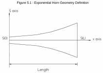
To reduce eventual work, I found the indication below related to the attached image, so it might be good enough. Could you check if it's aligned with Hornresp?
S(0) = The area at the throat (hornresp S1)
S(L) = The area at the mouth (hornresp S2)
m = Constant of the exponential horn (hornresp hidden parameter)
x = Axial length position (hornresp hidden parameter)
L = Total horn length (hornresp L12)
S ( x ) = S0 exp(m*x)
Looks like the first step is to determine the variable m to proper match S0 and SL as part fo the same horn segment. So, knowing m, we can calculate any cross section area.
m = ln(S(L)/S(0))/L
The cross section area S(x) is also = width*height
if the width is fixed (two parallels panels), dividing the cross section area S(x) by width we find the height.
Attachments
Hello David,
Just to make you aware and save time, unfortunately FreeCAD is not able to draw the exponential horn in a automated way that I could implement and share with other, the current available functionality requires some manual process, so I'm not going to implement soon. In order to improve this area in the future I open a thread in the FreeCAD requesting the functionality to draw a line based on a given equation. Lets see what futures bring. For a while it doesn't looks promising.
Thank you.
https://forum.freecadweb.org/viewtopic.php?f=8&t=75413
Hi Marcelo,
You could have easily checked for yourself 🙂. You will find that the results are identical.
To complete the picture,
For a conical horn:
R(0) = Sqrt(S(0) / Pi)
R(L) = Sqrt(S(L) / Pi)
R(x) = R(0) + x * (R(L) - R(0)) / L
S(x) = Pi * R(x) ^ 2
For a parabolic horn:
S(x) = S(0) + (S(L) - S(0)) * x / L
Note that the width does not necessarily have to be fixed for the above to apply.
Kind regards,
David
Could you check if it's aligned with Hornresp?
You could have easily checked for yourself 🙂. You will find that the results are identical.
To complete the picture,
For a conical horn:
R(0) = Sqrt(S(0) / Pi)
R(L) = Sqrt(S(L) / Pi)
R(x) = R(0) + x * (R(L) - R(0)) / L
S(x) = Pi * R(x) ^ 2
For a parabolic horn:
S(x) = S(0) + (S(L) - S(0)) * x / L
if the width is fixed (two parallels panels), dividing the cross section area S(x) by width we find the height.
Note that the width does not necessarily have to be fixed for the above to apply.
Kind regards,
David
FreeCAD is not able to draw the exponential horn in a automated way that I could implement and share with other, the current available functionality requires some manual process, so I'm not going to implement soon.
Where does this leave the feature requested in Post #13,309 - is it still required at this stage?
Last edited:
Over the years I have seen horns made out of everything from paper to concrete, but never before one made from seagrass and seaweed 🙂.

... and you can smoke it when you're done listening. 😉Over the years I have seen horns made out of everything from paper to concrete, but never before one made from seagrass and seaweed 🙂.
View attachment 1132801
🙄
is it still required at this stage?
No, we can let that request on-hold.
I was able to create a excell to generate the cloud points in the format FreeCAD needs, so It was easy to import the cloud points, but to make the points worth with the Sketch it wasn't so easy with many manual process 🙁 , lets see I FreeCAD developers brings some improvement in a feature.
Thank you to check.
Best Regards,
Marcelo
Hello David,
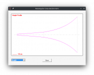
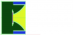
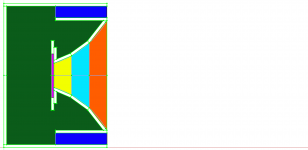
Good news, I was able to find a solution to create an exponential horn with FreeeCAD, and I made the first fully functional model, the Altec817. See attachments.
It's a discrete model using 10 segments witch I think is enough for loudspeakers but it isn't hard to increase or decrease the number of segments.
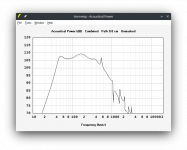
Compared to the current available model witch uses 3 parabolic segments circumscription with a fixes radius, the difference is minimal.
Black line = 1 Exponential Horn
Gray line = 3 Parabolic Horn
Good news, I was able to find a solution to create an exponential horn with FreeeCAD, and I made the first fully functional model, the Altec817. See attachments.
It's a discrete model using 10 segments witch I think is enough for loudspeakers but it isn't hard to increase or decrease the number of segments.
Compared to the current available model witch uses 3 parabolic segments circumscription with a fixes radius, the difference is minimal.
Black line = 1 Exponential Horn
Gray line = 3 Parabolic Horn
Attachments


No, we can let that request on-hold.
If the feature is required sometime in the future, it would be relatively easy to implement.
Hornresp Update 5450-230122
Hi Everyone,
CHANGE 1
The error trapping functionality has been extended to enable users to fix invalid Filter Wizard data problems by resetting the parameters to default values. The post linked below refers.
https://www.diyaudio.com/community/threads/hornresp-manual.383370/#post-7222548
CHANGE 2
The Save functionality associated with the Multiple Entry Horn Loudspeaker Wizard had serious limitations which hopefully have now all been addressed. My thanks to pelanj for highlighting the issue in Post #13,307.
BUG FIX 1
The CH1 Loudspeaker Wizard System Model Acoustic Circuit Diagram was not being displayed as intended. This has now been fixed. Post #13,279 refers.
BUG FIX 2
In the main results, the output from Horn 1 in a CH1 system was incorrectly called the Port output. This has now been fixed. Post #13,279 refers.
BUG FIX 3
The Path slider was not being made visible in the CH1 Loudspeaker Wizard. This has now been fixed. Post #13,279 refers.
Kind regards,
David
- Home
- Loudspeakers
- Subwoofers
- Hornresp