I would be surprised if there is much difference in performance between a circular cross-section and a square cross-section multiple entry horn system, provided that the flare rates and areas are similar for each. I suspect that the circular cross-section system could be a bit more difficult to construct, though 🙂.This I should actually make over the winter to see if there is much difference between a square Multiple entry horn and a cylindrical multiple entry horn.

As soon as you created the ‘ph one’ section, everyone was able to perfectly align quarter wave resonators at an odd harmonic, (much like the OD mode allows in that qw pipe layout at pi/9 or ~1/3) ) as well as the matching offset driver entry points within, and the whole layout started showing a system of numbers and wave lengths and distances that would(when incorporated together), created what resemble the ‘hexagon’. Or essentially units of time on a clock or intervals on a compass, etc..Hi Bw,
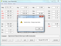
Thanks for the feedback, the bug will be fixed in the next update.
In the meantime, to get around the problem just set L45 to 0.10 rather than 0.01.
Incidentally, given your interest in the significance of numbers, if you have not already seen it, you might like the article linked below 🙂.
Why 21 cm is the magic length for the Universe
Kind regards,
David
In horn response these ‘perfect’ alignments will then show up as 0.0 phase or in SPL -990DB At the same locations that are trigonometric functions and stem from
A^2 plus B^2 Is C^2
B is 864
C is 864 x2
A is 864 • sqroot3
and ‘c’ is still ‘3’ or the speed of light as in E is mC^2…
and ‘a’ is the astronomical unit , ironically..
all while creating enclosures that had incredibly awesome uninterrupted bandwidth with no phase, hiccups or hard to drive (cone damage) areas of overlap from Parallel quarterwave pipes that didn’t make sense or work out mathematically, irrelevant by length or cross-sectional area that simply didn’t work otherwise, and were never able to be seen because there is no software that expresses these details so eloquently or precisely, while still keeping you safe outta excessive shapes or designs with no relevance to ‘useful‘ advantages otherwise (in qw pipe fun) @ 3:1
Attachments


Last edited:
Merry christmas everyone!
On ripole simulations, Vtc can not be set. Is that intentional?
E.g. on a flat open baffle it's possible, that's also a dipole.
Would it without too much work be possible to add the polar directivity pattern to the ripole speaker wizard?
On ripole simulations, Vtc can not be set. Is that intentional?
E.g. on a flat open baffle it's possible, that's also a dipole.
Would it without too much work be possible to add the polar directivity pattern to the ripole speaker wizard?
Hi rertrobaer,
And a very Merry Christmas and Happy New Year to you also!
Yes, it is intentional.
A flat open baffle design uses the normal Nd loudspeaker configuration code which means that the Vtc and Atc input boxes will be enabled in Edit mode in all cases, but any values entered will only be recognised if segment 1 is also included. This can be seen by checking the flat open baffle schematic diagram, or by confirming that the results do not change regardless of the throat chamber input values.
A ripole design is specified using the unique configuration code OD2, which means that Hornresp knows that Vtc and Atc should be disabled in this case.
I will have a look, and if it is not too much work I will try to include something in the next update.
Kind regards,
David
Merry christmas everyone!
And a very Merry Christmas and Happy New Year to you also!
On ripole simulations, Vtc can not be set. Is that intentional?
Yes, it is intentional.
E.g. on a flat open baffle it's possible, that's also a dipole.
A flat open baffle design uses the normal Nd loudspeaker configuration code which means that the Vtc and Atc input boxes will be enabled in Edit mode in all cases, but any values entered will only be recognised if segment 1 is also included. This can be seen by checking the flat open baffle schematic diagram, or by confirming that the results do not change regardless of the throat chamber input values.
A ripole design is specified using the unique configuration code OD2, which means that Hornresp knows that Vtc and Atc should be disabled in this case.
Would it without too much work be possible to add the polar directivity pattern to the ripole speaker wizard?
I will have a look, and if it is not too much work I will try to include something in the next update.
Kind regards,
David
Just confirming that the polar directivity pattern chart will be added to the ripole loudspeaker wizard in the next update.I will have a look, and if it is not too much work I will try to include something in the next update.
In this (german) article, it's claimed to get some sort of passive cardiod ripole speaker by reducing low frequencies on the rear output.
The front output segment has the same taper but more volume, the mouth area is the same for rear and front output.

Does someone here think this makes sense, or at least is some improvement for a ripole?
If so, would it be possible to add an additional segment to the ripole simulation that may abrupt reduces the mouth area?
The front output segment has the same taper but more volume, the mouth area is the same for rear and front output.
Does someone here think this makes sense, or at least is some improvement for a ripole?
If so, would it be possible to add an additional segment to the ripole simulation that may abrupt reduces the mouth area?
In this (german) article, it's claimed to get some sort of passive cardiod ripole speaker by reducing low frequencies on the rear output.
The front output segment has the same taper but more volume, the mouth area is the same for rear and front output.
If that is the extent of the secret sauce, a slanted baffle on an open cabinet I would say not a chance of shaping the dispersion of the driver. Especially in the bass region. The wavelengths are epicly longer than any cabinet dimension or even combination of dimensions. As an example 64 hertz. the region of greatest bass impact across all music genres is 16 feet long or 4.88 metres. Even half wavelength where you can do something is 2.44 metres. THis is why we say that subwoofers are omni directional. In large enough rooms they are directional. But few of us have Cathedrals or concert halls for listening rooms. Even with tuned resistive dampening I am very skeptical of there being any real shaping of the directional response.

Does someone here think this makes sense, or at least is some improvement for a ripole?
If so, would it be possible to add an additional segment to the ripole simulation that may abrupt redIf uces the mouth area?
My understanding was that it's more about the small mouth on the bigger volume in the kirchner ripole.
E.g. here is a TL with 8cm^1 mouth, when the mouth is reduced to 0.5cm^2, the output is about 3db reduced.

E.g. here is a TL with 8cm^1 mouth, when the mouth is reduced to 0.5cm^2, the output is about 3db reduced.
would it be possible to add an additional segment to the ripole simulation
The ripole design already uses all four available segments.
Hornresp Update 5450-230101
Hi Everyone,
CHANGE 1
Pressure response and polar directivity pattern charts have been added to the ripole loudspeaker wizard. Post #13,283 refers.
CHANGE 2
Previously the default path length for a ripole loudspeaker was the physical distance L12 + L23 separating the front and rear output ports. The default path length is now the distance between the two point source acoustic centres of the system. The length can still be manually set to L12 + L23 or any other value, if required.
BUG FIX 1
The bug reported in Post #13,275 has been fixed.
My thanks to Booger weldz for the feedback.
BUG FIX 2
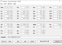
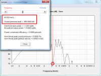
The main input parameters window was not processing ripole length values correctly. Values entered for L12 and L23 should have been copied into L34 and L45 respectively, but this was not happening. Fatal errors could also sometimes occur as shown in the Attachment. These bugs have now been fixed.
Kind regards,
David
Hi Everyone,
CHANGE 1
Pressure response and polar directivity pattern charts have been added to the ripole loudspeaker wizard. Post #13,283 refers.
CHANGE 2
Previously the default path length for a ripole loudspeaker was the physical distance L12 + L23 separating the front and rear output ports. The default path length is now the distance between the two point source acoustic centres of the system. The length can still be manually set to L12 + L23 or any other value, if required.
BUG FIX 1
The bug reported in Post #13,275 has been fixed.
My thanks to Booger weldz for the feedback.
BUG FIX 2
The main input parameters window was not processing ripole length values correctly. Values entered for L12 and L23 should have been copied into L34 and L45 respectively, but this was not happening. Fatal errors could also sometimes occur as shown in the Attachment. These bugs have now been fixed.
Kind regards,
David
Attachments
Hello David,
Do you mind to check the post below (#32) once the user was able to measure both loudspeaker output (6th Order Bandpath Parallel) and looks like the output from the front horn shown cancelling frequencies not catchy from hornresp simulation. Do you know the reason for the simulation not detecting it? maybe the model is wrong, but it looks very simple and straight forward. I made some assumptions but the user didn't go deeper to check so I came here to ask for your help in the simulation part.
https://www.diyaudio.com/community/...dance-measurements.392495/page-2#post-7184970
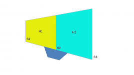
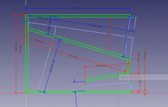
In the attached image, there is a very simple offset drive horn, and I think the size of S1 play and important role in the cancellation frequencies regarding the placement of the driver (S2), do you have suggestion, concern, or any hornresp limitation when using this model?
Do you mind to check the post below (#32) once the user was able to measure both loudspeaker output (6th Order Bandpath Parallel) and looks like the output from the front horn shown cancelling frequencies not catchy from hornresp simulation. Do you know the reason for the simulation not detecting it? maybe the model is wrong, but it looks very simple and straight forward. I made some assumptions but the user didn't go deeper to check so I came here to ask for your help in the simulation part.
https://www.diyaudio.com/community/...dance-measurements.392495/page-2#post-7184970
In the attached image, there is a very simple offset drive horn, and I think the size of S1 play and important role in the cancellation frequencies regarding the placement of the driver (S2), do you have suggestion, concern, or any hornresp limitation when using this model?
Attachments
Do you mind to check the post below (#32)
It is difficult to comment on the results without knowing how closely the actual physical design and dimensions of the loudspeaker match the Hornresp model and input values used in the simulation.
Hello David,
I remembered he shared the model in a different thread.
From the speed he built it, I don't think he made any additional tuning so, you can use it for a critical assessment. Anything related to a potential frequency cancellation in a offset horn might be very useful.
These data were attached in the posts #8 and #11 in the link below.
https://www.diyaudio.com/community/...-better-than-tapped-horn.391782/#post-7168668
I can reverse engineering this model if you need any other specific data not available in the attachment.
The driver used is the JBL 2217.
Attachments
Hi there all and a happy new year with a lot of bass.
David. I did a 6th orde bandpass with a vistaton wsp26s woofer, I did see it peaks when I want higher then 10 hz or so, this speaker does 10 to 90 hz or so in a 6th orde bandpass, I did try from20 a 25 hz butr that will not be reached in tuning.
I think this high Vas speaker with a lot of air displacement will not work from there but does subfrequencies well and has a wide respons.
The Qts does have also inpact because of the double tuning, with a 4th orde it does go higher as a start frequency.
Looks like it do get lower as a tapped horn without the high efficienty of these or I do something wrong.
regards
Attachments
Hello David,
I remembered he shared the model in a different thread.
From the speed he built it, I don't think he made any additional tuning so, you can use it for a critical assessment. Anything related to a potential frequency cancellation in a offset horn might be very useful.
These data were attached in the posts #8 and #11 in the link below.
https://www.diyaudio.com/community/...-better-than-tapped-horn.391782/#post-7168668
I can reverse engineering this model if you need any other specific data not available in the attachment.
The driver used is the JBL 2217.
Attachments
Hi Marcelo,
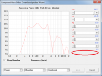
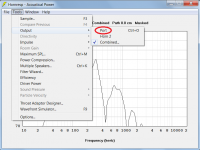
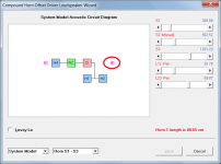
The only things I could find were that the CH1 Loudspeaker Wizard System Model Acoustic Circuit Diagram is not being displayed as intended, that the output from Horn 1 in a CH1 system is incorrectly called the Port output in the main results, and that the Path slider is not being made visible in the CH1 Loudspeaker Wizard. These three bugs, which do not affect the results, will be fixed in the next update.
Apart from the bugs everything else appears to be working just fine and I have no idea why there should be such a difference between the predicted and measured results.
Altering the S1 area will definitely affect the results, but as far as I am aware there is no limitation in the Hornresp offset driver model that would explain the discrepancy being seen.
Thanks, and a Happy New Year to you also!
Kind regards,
David
Do you mind to check the post below (#32) once the user was able to measure both loudspeaker output (6th Order Bandpath Parallel) and looks like the output from the front horn shown cancelling frequencies not catchy from hornresp simulation. Do you know the reason for the simulation not detecting it? maybe the model is wrong, but it looks very simple and straight forward.
The only things I could find were that the CH1 Loudspeaker Wizard System Model Acoustic Circuit Diagram is not being displayed as intended, that the output from Horn 1 in a CH1 system is incorrectly called the Port output in the main results, and that the Path slider is not being made visible in the CH1 Loudspeaker Wizard. These three bugs, which do not affect the results, will be fixed in the next update.
Apart from the bugs everything else appears to be working just fine and I have no idea why there should be such a difference between the predicted and measured results.
In the attached image, there is a very simple offset drive horn, and I think the size of S1 play and important role in the cancellation frequencies regarding the placement of the driver (S2), do you have suggestion, concern, or any hornresp limitation when using this model?
Altering the S1 area will definitely affect the results, but as far as I am aware there is no limitation in the Hornresp offset driver model that would explain the discrepancy being seen.
Hey David, I forgot to wish you and other member a happy new year.
Thanks, and a Happy New Year to you also!
Kind regards,
David
Attachments
Last edited:
Hello David,
Thanks to check, for sure there is nothing wrong with hornresp and probably is just me lacking in terms of knowledge.
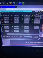
If i may ask for further detail. Check the attached image. I'm still using the same model from laxandredeyed. And I set the hornresp to show only the Horn output (rear chamber suppressed). Them I prepared 3 different cases regarding L12/S2 (driver placement inside off-set horn).
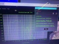
Hornresp is predicting "cancellation" effect (don't know if this is the right word) as indicating below:
when L12 = ~0,2m = a cancellation happen @ 462Hz
when L12 = ~0,3m = a cancellation happen @ 323Hz
when L12 = ~0,4m = a cancellation happen @ 250Hz
All frequencies below 150Hz are basically not affected from the driver placement, only higher frequencies. Probably there is something wrong with his measurement.
What is the physics / correlation between the L12 placement and the dip (cancellation) we see in the SPL curve for the offset horn only?
the 1/4WL thing does not properly match here.
0,2m is a wave length of 1700Hz or 1/4WL of 425Hz
0,3m is a wave length of 1133Hz or 1/4WL of 283Hz
0,4m is a wave length of 850Hz or 1/4WL of 213Hz
Thanks to check, for sure there is nothing wrong with hornresp and probably is just me lacking in terms of knowledge.
If i may ask for further detail. Check the attached image. I'm still using the same model from laxandredeyed. And I set the hornresp to show only the Horn output (rear chamber suppressed). Them I prepared 3 different cases regarding L12/S2 (driver placement inside off-set horn).
Hornresp is predicting "cancellation" effect (don't know if this is the right word) as indicating below:
when L12 = ~0,2m = a cancellation happen @ 462Hz
when L12 = ~0,3m = a cancellation happen @ 323Hz
when L12 = ~0,4m = a cancellation happen @ 250Hz
All frequencies below 150Hz are basically not affected from the driver placement, only higher frequencies. Probably there is something wrong with his measurement.
What is the physics / correlation between the L12 placement and the dip (cancellation) we see in the SPL curve for the offset horn only?
the 1/4WL thing does not properly match here.
0,2m is a wave length of 1700Hz or 1/4WL of 425Hz
0,3m is a wave length of 1133Hz or 1/4WL of 283Hz
0,4m is a wave length of 850Hz or 1/4WL of 213Hz
Attachments
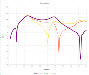
What is the physics / correlation between the L12 placement and the dip (cancellation) we see in the SPL curve for the offset horn only?
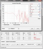
If the offset driver horn has a cylindrical profile then the dip in the horn output will be at the frequency where the offset length L12 is exactly equal to 1/4 wavelength. For example, if L12 is 20 cm and the speed of sound is assumed to be 34400 cm/sec then the cancellation will be at (34400/20)/4 = 430Hz as shown in the attachment.
If the offset driver horn is flared or tapered, then the analysis becomes more complex and the position of the dip can vary somewhat, depending upon the actual profile of the horn.
I see that laxandredeyed has now found an error in the L12 value used in the original simulation. It's no wonder that the measured and predicted results did not match 🙂.
https://www.diyaudio.com/community/...dance-measurements.392495/page-2#post-7225462
Attachments
Thank you David,
So for non cylindrical profile the 1/4 WL we can use just as a raw approximation. Very clear.
Unfortunately he changed the the model compared to what he shared, and in addition he also change dimensions during constructions leading to a mismatch results. But now everything is well understood. I'm liking a lot of Manifold-MTB design.
Thank you again to engage some amount of your time in this subject.
- Home
- Loudspeakers
- Subwoofers
- Hornresp