It's been a team effort 😊Here here! I think Stuart is on the road to creating one of the finest build guides in all of diyaudio! Kudos!
Best,
Anand.
I'm actually marking my copy up as I go and taking new up to date photos.
Once I'm finished building my amplifier I'll update the entire document with my notes and new images.
Last edited:

I could not wait to finish the Amp and took another day off. I soldered the output transistors and started testing. All LEDs went on, all test points measured as they should but the bias measurement showed 0.000 V DC. From reading the build guide I thought that there should be at least a tiny amount of bias with the trimmer R109 set to 200 ohms. But after spending some hours of checking different things and staring at the schematic I realised that the simulation data in the schematic shows R109 set to 32 ohms. So I tried to power the amp with R109 set to 90 ohms and I got a reading of 1mV. At this setting the bias trimmer reacted pretty fast and it was easy to achieve 44mV.
After letting it sit for a while I adjusted bias again and again, until it stop drifting. The DC offset was still at 1mV after the bias calibration.
First quick listening tests showed that the amp sounds great. With inputs shorted the amp is dead quiet. But with my dodgy B1ish buffer / Attentuator I have a faint hum that I did not have with my recent Aleph builds. So I will investigate that, using the documents about amp wiring and ground loops.
@AddiDub I'm glad that you have successfully got your amplifier up and running. Please post some images of your chassis.
Also, please short the inputs from the RCA connectors on the chassis and then measure the AC voltage on the speaker outputs binding posts. Please post these numbers here to.
Also, please short the inputs from the RCA connectors on the chassis and then measure the AC voltage on the speaker outputs binding posts. Please post these numbers here to.
Output device choices: in the UK at least the 2SC5200 / 2SA1943 from Profusion are quite a bit cheaper than the other options. Is this a case of, “you get what you pay for” ? This appears to be an exceptional amp and I don’t want to compromise its performance for the sake of saving say £50, but on the other hand there is no point in wasting money for little or no gain (ha ha see what I did there 😊 ). Your thoughts please.
I used the Onsemi 2SC5200 / 2SA1943 on one of our prototypes and they preformed exceptionally well. I can't comment on the ones from Profusion.Output device choices: in the UK at least the 2SC5200 / 2SA1943 from Profusion are quite a bit cheaper than the other options. Is this a case of, “you get what you pay for” ? This appears to be an exceptional amp and I don’t want to compromise its performance for the sake of saving say £50, but on the other hand there is no point in wasting money for little or no gain (ha ha see what I did there 😊 ). Your thoughts please.
@stuartmp inputs shorted I measure 0.001 V of AC on speaker outputs. That's the edge of the measuring range of my cheap multimeter. So no exact info about this.
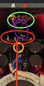
Okay, here are some crappy pictures. The two Toroids of my dual mono supply are stacked on top of each other. In real life the Amp looks a lot more crowded. Compared to @fireanimal amp with its "small" SMPS, a linear dual mono power supply with individual soft start boards and cap banks takes a lot of space.

Some details:

Green circles on the bottom of the picture:
Soft start devices for the transformers
Yellow circle: common safety ground / mains earth to chassis connection
Red circle: power inlet with additional fuses for each PSU Channel
Red line: 230V mains cable underneath the base plate

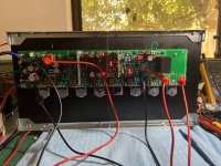
A second perspective. At the upper left corner you can see the black Audio input wire cross the 230V AC area that is located at the front panel of my enclosure. I could try other ways to route the input wires. But I hope that I can leave most of the other wiring as is, because I put a lot of effort in dressing the cables..
Okay, here are some crappy pictures. The two Toroids of my dual mono supply are stacked on top of each other. In real life the Amp looks a lot more crowded. Compared to @fireanimal amp with its "small" SMPS, a linear dual mono power supply with individual soft start boards and cap banks takes a lot of space.
Some details:
Green circles on the bottom of the picture:
Soft start devices for the transformers
Yellow circle: common safety ground / mains earth to chassis connection
Red circle: power inlet with additional fuses for each PSU Channel
Red line: 230V mains cable underneath the base plate
A second perspective. At the upper left corner you can see the black Audio input wire cross the 230V AC area that is located at the front panel of my enclosure. I could try other ways to route the input wires. But I hope that I can leave most of the other wiring as is, because I put a lot of effort in dressing the cables..
About the faint hum: with inputs shorted I only can hear it with my ears as near to the speaker as possible. You have to know that there is hum to hear it..
About the noise from my sources: the hum from my sources gets worse if I touch the metal volume control knob of my smps driven B1 buffer (that has no own mains ground reference). I think the hum has been there before, but I did not hear it because my gain structure was different. The Pass style amps I have build have a voltage gain of 15 dB, which is plenty enough for those 25 watt amps. The Wolverine needs more gain in order to achieve its maximum output power in the high rail voltage versions. Because of the high gain of the Wolverine I have to attentuate the Input signal more, which degrades the total signal to noise ratio of my audio chain. To say it in a polemic way: now I am able to listen to the noise of my sources without the amplifier distorting it 🤡
Conclusion: the Wolverine is a very good amplifier to start tweaking the rest of the chain..
Looks great and measures well. The final test will be put your ear to your tweeter and listen for hiss.@stuartmp inputs shorted I measure 0.001 V of AC on speaker outputs. That's the edge of the measuring range of my cheap multimeter. So no exact info about this.
Okay, here are some crappy pictures. The two Toroids of my dual mono supply are stacked on top of each other. In real life the Amp looks a lot more crowded. Compared to @fireanimal amp with its "small" SMPS, a linear dual mono power supply with individual soft start boards and cap banks takes a lot of space.
View attachment 1123835
Some details:
View attachment 1123836
Green circles on the bottom of the picture:
Soft start devices for the transformers
Yellow circle: common safety ground / mains earth to chassis connection
Red circle: power inlet with additional fuses for each PSU Channel
Red line: 230V mains cable underneath the base plate
View attachment 1123841
A second perspective. At the upper left corner you can see the black Audio input wire cross the 230V AC area that is located at the front panel of my enclosure. I could try other ways to route the input wires. But I hope that I can leave most of the other wiring as is, because I put a lot of effort in dressing the cables..
What are the black wires in my purple circle for? Are they the shields from your input wires?
If so how are they terminated at each end etc...
Personal I would have the amplifier modules flipped so my input signal wires are shorter. But everything else you have done is spot on.
Well done.
Attachments
@stuartmp
- I build all of my other amplifiers like you suggest. This time I tried to keep the DC rail power cables as short as possible. I don't think I will find the time to re-arrange everything soon.
One other thing: My build does pop/crack very loud while switching it on. I don't now if this is normal with the Wolverine, but I will implement a speaker turn-on Delay / DC protection board as soon as possible.
- No hiss at all with inputs shorted. Nothing
- Hiss and maybe RF when B1ish buffer and / or the phono preamp is connected and volume is set to max
- the black wires are the ends of the shields of the audio input wiring. I used some shielded microphone cable I had. I tried bonding the shields together and connecting it to the chassis but hum got worse (I think).
- I build all of my other amplifiers like you suggest. This time I tried to keep the DC rail power cables as short as possible. I don't think I will find the time to re-arrange everything soon.
One other thing: My build does pop/crack very loud while switching it on. I don't now if this is normal with the Wolverine, but I will implement a speaker turn-on Delay / DC protection board as soon as possible.
Hi Addidub,@stuartmp
The shield is currently not connected to the IPS. I am willing to rework the Audio input wiring in any suggested way.
- No hiss at all with inputs shorted. Nothing
- Hiss and maybe RF when B1ish buffer and / or the phono preamp is connected and volume is set to max
- the black wires are the ends of the shields of the audio input wiring. I used some shielded microphone cable I had. I tried bonding the shields together and connecting it to the chassis but hum got worse (I think).
- I build all of my other amplifiers like you suggest. This time I tried to keep the DC rail power cables as short as possible. I don't think I will find the time to re-arrange everything soon.
One other thing: My build does pop/crack very loud while switching it on. I don't now if this is normal with the Wolverine, but I will implement a speaker turn-on Delay / DC protection board as soon as possible.
Great looking amplifier build !
Are you using a loop breaker to connect audio earth to chassis ?
Just wondering since I didnt see one.
Well done with your amplifier so far !
- Dan
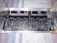
@danieljw Yes, I got ground loop breakers installed, it's hard to spot them on the pictures of the finished amp. Here is a picture before assembly that shows how the PSU section is wired.

Again, thanks to everyone involved! Especially to the ones who created and edited the BOM..
Again, thanks to everyone involved! Especially to the ones who created and edited the BOM..
Hi Addidub,@danieljw Yes, I got ground loop breakers installed, it's hard to spot them on the pictures of the finished amp. Here is a picture before assembly that shows how the PSU section is wired.
View attachment 1124140
Again, thanks to everyone involved! Especially to the ones who created and edited the BOM..
Just something to consider;
You can put a 10 ohm 3W or 5W metal film in parallel with your ground lift and a cap of 10nF to 100 nF (250Vac rated) also in parallel.
The link below has some more info on this topic.if you like: https://sound-au.com/earthing.htm#s9
Hope this helps
- Daniel
If you are getting hum when you touch the volume control knob what may be happening is you are coupling HF noise into the front end circuit. This comes down the pot metal shaft and then capacitively couples into the pot track or resistor network This HF field will be modulated by any mains mag field (via your body picking it up, or a nearby 50/60 Hz transformer) which then gets demodulated by base emitter functions in the amp or preamp gain stages. This kind of problem can also happen if some part of the circuit oscillates.About the faint hum: with inputs shorted I only can hear it with my ears as near to the speaker as possible. You have to know that there is hum to hear it..
About the noise from my sources: the hum from my sources gets worse if I touch the metal volume control knob of my smps driven B1 buffer (that has no own mains ground reference). I think the hum has been there before, but I did not hear it because my gain structure was different. The Pass style amps I have build have a voltage gain of 15 dB, which is plenty enough for those 25 watt amps. The Wolverine needs more gain in order to achieve its maximum output power in the high rail voltage versions. Because of the high gain of the Wolverine I have to attentuate the Input signal more, which degrades the total signal to noise ratio of my audio chain. To say it in a polemic way: now I am able to listen to the noise of my sources without the amplifier distorting it 🤡
Conclusion: the Wolverine is a very good amplifier to start tweaking the rest of the chain..
The coupling path can be via HF noise on the incoming mains power cables, directly from the PSU (transformer or traces to and from the mosfet switching device) or just as HF noise on the switching PSU output. As a first step you could try moving your switching PSU. If there is a dramatic change in the level you are hearing it may be direct coupling. If the PSU is remote (wall wart) try some additional filtering. I believe Mark Johnson has some solutions for that.
AddiDub - Make sure that the metal enclosure is connected to the signal ground. I had the same problem (on a completely different amplifier) because the enclosure sides were electrically floating.
Ed
Ed
- the black wires are the ends of the shields of the audio input wiring. I used some shielded microphone cable I had. I tried bonding the shields together and connecting it to the chassis but hum got worse (I think).
(BTW connecting the shield to the chassis in a balanced input system is the correct thing to do, but not in a single ended unbalanced system)
Τhe boards were fixed. One down one up .The inputs back to the box the DC supplies in front together with the transformer.Which will be placed vertically together with the soft start and Dc trap board.Tomorrow I will drill the holes for the output transistors.
Attachments
Nikos, could you tell me how and where i can find those boards that you use in the power supply?Τhe boards were fixed. One down one up .The inputs back to the box the DC supplies in front together with the transformer.Which will be placed vertically together with the soft start and Dc trap board.Tomorrow I will drill the holes for the output transistors.
- Home
- Amplifiers
- Solid State
- DIY Class A/B Amp The "Wolverine" build thread