Member
Joined 2009
Paid Member
Hi Gareth,
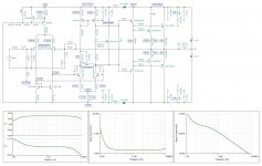
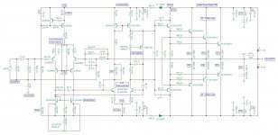
This is a variant of ODNF (Only Distortion Negative Feedback).
The idea is that he subtracts the input signal from the output signal, resulting in the error signal, normalizes its amplitude (U2), and then subtracts the error signal from the total (input + error) signal (U1), reducing the distortion.
Thanks Valery ! - after all these years I finally find out the secret
Is it like Class S ?
Last edited:
Does that mean that ODNF is some kind of feedforward error correction?
Hi Ivanlukic,
If we look at it from the overall concept point of view - ODNF is still the kind of a feedback, not feedforward.
You can also look at it in the following way:
- Initially, we've got an amplifier with no global feedback loop, gain = 29db, providing some level of distortion (low enough).
- As soon as we add ODNF circuit, we increase the gain by +18db (small signal distortion increase is low) and then kill that additional 18db gain with 18db global feedback, together with the overall level of distortion, decreasing the overall output impedance by that volume as well.
As a result, we preserve the initial amplifier's character (distortion profile), decreasing the absolute level of distortion by the global feedback loop gain (almost), provided by ODNF circuit (18db in my implementation).
The thing works well if the initial amplifier is linear enough by itself so that the ODNF loop gain is not too high (say, 20db or so).
Thanks Valery ! - after all these years I finally find out the secret
Is it like Class S ?
Well, it's similar nature in a way that there are some [higher-quality / small signal / low power] and [lower-quality / big signal / high power] amplifiers and they assist each other 🙂
Although, ODNF mechanism is different from the one for class S.
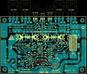
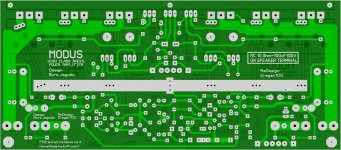
........ I have layout one of many great design of Dr.Bora J , T REFERENCE AMPLIFIER 😉 for people who intend to build . 🙂
Alex.
Is there a mistake on this pcb? At the schematic, there are two 1uF input capacitors ( which equal to 2uF, understood ) but at the pcb layout there are two 1uF caps in parallel on the left of the input pin and another two in the place of the 2.2uF cap, which are in parallel too, but not connected to the input path on the right side ( where the single 2.2uF would sit and make contact ). Am I missing something?
One more thing, what would be the value of the output coil?
Thanks in advance.
Attachments
Last edited:
You can use what you want, in schematic there is 2x 1uF 🙂
So much place to use one big good 2,2uF, like jantzen cap MKT/MKT or something like that 🙂
So much place to use one big good 2,2uF, like jantzen cap MKT/MKT or something like that 🙂
Of course I would of used either the top two 1uf caps or the one spot for the 2.2uF but it was kind of funny the indication of two 1uf caps in the place of the 2.2uF with them not being connected to the input, so I wanted to be sure if there is a mistake or the pcb designer had something else in mind. Anyway, I will erase the unnecessary tracks on the 2.2uF spot.
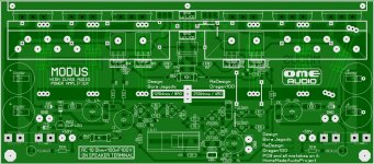
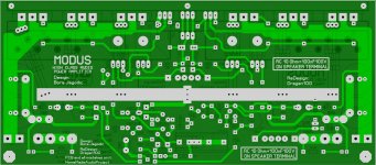
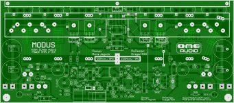
it is just work in progress,based on one of most popular Bora's amplifiers named Modus aka Techno. SymAsym is amazingly similar later version,i have built it and it sounds amazing-but all those that have built or listened SymAsym and Modus\Techno have had an agreement that there's something better about Bora's Modus\Techno. i have never heard Techno in it's origin,but in ex Yugoslavia we have quite a bit of engineers that were willing to even improve characteristic of late Bora's invention,and there are two versions.one with all 2SA 2SC transistors in IPS VPS IPS,and another with BCxy 2Nxy1 in IPS and all other 2SA 2SC transistors. everything is still work in progress- Dragan 100 is an engineer and I am drawing a PCB. when everything is made,checked and confirmed as "working case" i will post pictures, schematics and video's. until than...
Last edited:
untill then... Work In Progtess 🙂
Attachments

Last edited:
Hi,
I liked to ask if anyone built a Sigma or Delta amplifier?
Could someone please post the PCB to Delta?
What are Yours thoughts on the Sigma amplifier? I am asking because I have 2 modules, 3 pairs of 2sj 48 / 2sk 133 each and I am thinking of applying them to Sigma.
Darek
I liked to ask if anyone built a Sigma or Delta amplifier?
Could someone please post the PCB to Delta?
What are Yours thoughts on the Sigma amplifier? I am asking because I have 2 modules, 3 pairs of 2sj 48 / 2sk 133 each and I am thinking of applying them to Sigma.
Darek
some building up of techno-modus amplifier - work in progress. based on BoraOmega's legacy:
Did you ever finish up this one?
Ermm...cough...btw, there's now such thing as Yugoslavia. Yugoslavia is dead as a Dodo bird ! Let it stay that way !
I have reached the point where I must drill some aluminum to completely finish both versions of an amplifier - but I haven't done it yet. I will probably do it in next month or so,when i do something I will post it here. hopefully soon!Did you ever finish up this one?
Thank God Yugoslavia is dead,but topic has no need to be.Ermm...cough...btw, there's now such thing as Yugoslavia. Yugoslavia is dead as a Dodo bird ! Let it stay that way !

it is just work in progress,based on one of most popular Bora's amplifiers named Modus aka Techno...
Pics?
- Home
- Amplifiers
- Solid State
- Bora is a nice guy from Serbia - Yugoslávia