Nobody - OK, I - was questioning anything about your level of expertise or any of that.I know. Do you think he is the only guy who has ever had to do anything like that for living? Okay, what I did was for experimental neutron Radiation Oncology, not high energy physics research, but I have seen a reasonable share of problems with low level signals and noise. IME audio is a different type of thing. When measurements numbers are small and below the threshold of audibility for 50% of the population, some people like to believe only large numbers are plausible. Whatever it is the particular person can hear, possibly on their particular system or on various systems. Know what I mean?
Last edited:
You claim PTs generate noise?
Wow!!!!
And which would be the noise generation mechanism?
There's been a number of articles on this subject. Most were in the professional press because of EMI requirements for power supplies, especially switchers, but some have been in articles aimed toward audio guys.
Here's a couple of the latter:
Hagerman on Snubbers
Johnson on Soft Recovery Diodes
My own opinion, which works for me and maybe nobody else, is to use rectifier diodes that have the best reverse recovery characteristics. That minimizes the kind of switching noise and stuff that can get coupled into other parts of the amplifier or whatever circuit through electromagnetic means. Then, also apply the right damping network across the transformer secondary to eliminate the ringing in the RLC circuit formed with the transformer. Pretty simple and pretty cheap. What harm is there in that? Seems like good design practice. The power supply expert at my day job takes that approach, and we do nothing with audio products.
I also use power filters into every piece of gear. This reduces both differential mode signals that I don't want going into (and out of) each piece of equipment as well as common mode signals that couple through the AC mains.

Yes, for bonding to a metal chassis. That's not necessarily the same thing as the audio circuit common. No more than if the audio circuit were class B, double insulated....code specifies bonding impedance levels for a reason...
Last edited:
In the medical field, you are highly constrained in how you can deal with electrical noise issues. The standards are quite strict.I know. Do you think he is the only guy who has ever had to do anything like that for living? Okay, what I did was for experimental neutron Radiation Oncology, not high energy physics research, but I have seen a reasonable share of problems with low level signals and noise. IME audio is a different type of thing. When measurements numbers are small and below the threshold of audibility for 50% of the population, some people like to believe only large numbers are plausible. Whatever it is the particular person can hear, possibly on their particular system or on various systems. Know what I mean?
I cannot imagine you being allowed to modify equipment in any fashion, so you must have been limited to what was approved for use.
I also cannot imagine how a neutron beam (neutral particles) could be affected by anything other than stuff in the way (nuclear cross section).
You must have been involved in the detection electronics. But again, really hamstrung by regulation.
I do some stuff for high energy physics, but also for synchrotron x-ray generation as well as helping out on the beamline end station electronics...among other stuff too cool to talk about..
In my work, I am absolutely allowed to modify equipment (or recommend such) to alleviate issues caused by EMC problems. I don't live under the human life safety stuff (you had to live with) for under the hood mods. As long as I can convince the AHJ that it meets NEC, he's good with that.
I force the experimenters and scientists to meet code, and them show them how to get around the problems caused by code.. Fun stuff.
John
ps... NEC, AHJ, EMC....acronyms are just so cool. Makes me look like I actually understand stuff..
You have got to be kidding. I said experimental. This was a one off system funded by NCI and located at a well known US university. It was approved for research. Patients were fully informed of known risks and that there might be unknown risks. We made it very safe. The main risk was that the doctor could not know how to best prescribe treatment since there wasn't a lot of research data on fast neutron therapy to guide them at the time. That's why we were there, so that there could be some research data.I cannot imagine you being allowed to modify equipment in any fashion, so you must have been limited to what was approved for use.
Exactly. Any metal surface that could be energized must be bonded.Yes, for bonding to a metal chassis. That's not necessarily the same thing as the audio circuit common. No more than if the audio circuit were class B, double insulated. A device could still have exposed RCA connector commons, but they are not necessarily considered to be a chassis for regulatory safety purposes.
For example, if one audio object suddenly becomes hot to ground (perhaps the internal hot conductor violated the recommended minimum bend radius and the insulation cracked with age, allowing the hot conductor to energize the chassis to 120 volts), and some wimpy ill designed "ground isolator" pops the bridge, leaving two independent chassis 120 volts AC apart DESPITE there being an RCA cord between the units). Do you notify next of kin? Do I?
While an object may have a 1 amp fuse, is it built into the IEC input, or is it independent and wired?
The problem is when a random circuit that could impact safety is recommended to DIY audio guys on an internet forum. Are you confident that the person listening to the recommendations actually understands the entire scenario?
I am not. Nor would I ever recommend a safety work around like that. Reality is, it needs to be engineered properly.
John
This thread is frothy.
So, has any power conditioner currently available in the marketplace been proven to improve line AC yet?
My smart friends tell me more than half actually make things worse. The other half improves things for equipment that lacks very basic, cheap power regulation parts.
I have no clue, but I could use a bench solution that would guarantee I am measuring what I think I am measuring.
I do not kid about safety.You have got to be kidding. I said experimental. This was a one off system funded by NCI and located at a well known US university. It was approved for research. Patients were fully informed of known risks and that there might be unknown risks. We made it very safe. The main risk was that the doctor could not know how to best prescribe treatment since there wasn't a lot of research data on fast neutron therapy to guide them at the time. That's why we were there, so that there could be some research data.
Our discussion was about electrical equipment bonding. If you were allowed to modify safety bonding at whim without oversight I would be surprised.
Neutron energy/depth of penetration, z cross section...I get it, it's all experimental. But the electronics, not so much so.
What effort was required by you to alleviate safety bonding induced noise issues? Did you have to go into medical equipment to break ground loops? Did you have to modify the room AC power distribution to minimize inductive pickup, reduce stray currents? Your experience in this regard would be of merit to me, I enjoy understanding the problems and solutions of others.
jn
That I did have to do, since I was engineer responsible for the equipment design at the time, although some of its design history predated me. An ECO was issued for the change by me, and approved by the ECO review committee. Product documentation was updated to reflect the design change. All done properly.Did you have to go into medical equipment to break ground loops?
The other wild stuff you described was never considered for any reason, nor would it have been.
Again, the discussion here is about a piece of circuitry sometimes used in consumer audio equipment and which has passed existing regulatory approval in the US, Canada, and EU. You don't have to like it, and you have made it plain that you don't. Fine.
Last edited:
Thanks, and good to know, but I was asking Transformers and how they can generate noise, not switchers (of which diodes are a particular case).There's been a number of articles on this subject. Most were in the professional press because of EMI requirements for power supplies, especially switchers, but some have been in articles aimed toward audio guys.
Here's a couple of the latter:
Hagerman on Snubbers
Johnson on Soft Recovery Diodes
My own opinion, which works for me and maybe nobody else, is to use rectifier diodes that have the best reverse recovery characteristics. That minimizes the kind of switching noise and stuff
Self quoting:
You claim PTs generate noise?
Wow!!!!
And which would be the noise generation mechanism?
Thanks, but again I am asking Transformers generating noise and I am answered other elements doing switching (including diodes).The haversine currents on the primary during high power delivery to the speakers will generate lots of harmonics, a cap could help dull those out a bit.
Also, some diodes do tend to switch off in weird ways. Some turn off soft, some very hard. Even within a single product line, different diffusion runs can exhibit different behaviour.
Also, during diode conduction to recharge caps, HF audio currents can work back into the transformer. (which is not the same as the transformer generating anything) It acts like a gating mechanism. If the caps are small, large droop gives longer gating times. Larger caps give higher haversine currents but less droop.
Not holding my breath, this is a cable thread and Shunyata marketing thread after all.
Used Monster HTPS 7000 Mk II, possibly from ebay. IMHO still one of the best. Designed for Monster by a couple of forum members, as it happens. Have one on the bench and one for the stereo here. They use a combination of multiple circuits with common mode chokes and couple of circuits also having back to back isolation transformers. For safety reasons the transformer isolated AC outlets are protected by GFIs.So, has any power conditioner currently available in the marketplace been proven to improve line AC yet?
Last edited:
Let me reveal a big trade secret: a transformer's core business is something called a "magnetic field", and that thingy loves to go out and play. 🙂Thanks, but again I am asking Transformers generating noise and I am answered other elements doing switching (including diodes).
...
👍Nor would I ever recommend a safety work around like that. Reality is, it needs to be engineered properly.
John
👍Again, the discussion here is about a piece of circuitry sometimes used in consumer audio equipment and which has passed existing regulatory approval in the US, Canada, and EU. You don't have to like it, and you have made it plain that you don't. Fine.
Loop breaker circuit from post #359 is great in principle but has one fatal flaw. It recommends 2A rated bridge. Single cycle pulse current would be about 20A and this is not safe enough. Bridge has to survive, if required, burning main house fuses. Diodes in that circuit variant are connected in series. Much better is to have two in parallel like this: https://sound-au.com/earthing.htm
I’m using 45A rated bridge with 450A pulse current. Two diodes in parallel will sustain 900A for full 16 ms. That will burn any fuse except nail.
With diodes instead of NTC, we can safely use higher value resistor. I have 100Ω in preamplifier and 47Ω in power amplifier. That reduces any power cords effect and hum because of ground loops, as is visible from measurements in post #107.
True , but how would that inject noise into Mains?Let me reveal a big trade secret: a transformer's core business is something called a "magnetic field", and that thingy loves to go out and play. 🙂
We are not talking a microphone input transformer placed 1 inch away but gross noise generated by PT, injected back into Mains, and magically stopped by a Knight in shining armor .
Sorry, a Shunyata thingie.
EDIT: you-can´t-make-this-stuff-up. 😱
Out of curiosity, I googled the Shunyata word.
And what was the answer?
Didn´t they research the word before applying for the brand or is it just a tongue in cheek reconnaissance of what they sell? 😱Śūnyatā (Sanskrit: शून्यता, romanized: śūnyatā; Pali: suññatā; English: /ʃuːnˈjɑː.tɑː/ shoon-YAH-tah), [2translated most often as emptiness,[1] vacuity, and sometimes voidness,]
In Mahāyāna Buddhism, śūnyatā refers to the tenet that "all things are empty of intrinsic existence and nature (svabhava)",[4][5] but may also refer to the Buddha-nature teachings and primordial or empty awareness, as in Dzogchen, Shentong, or Chan.
Last edited:
There are other good articles as well:There's been a number of articles on this subject. Most were in the professional press because of EMI requirements for power supplies, especially switchers, but some have been in articles aimed toward audio guys.
Here's a couple of the latter:
Hagerman on Snubbers
Johnson on Soft Recovery Diodes
https://sound-au.com/articles/psu-snubber.htm
This sums it up quite well:
"This is an article where, in an attempt to prove that something was completely unnecessary, I discovered that this may not be the case. However, I also found nothing to suggest that a snubber is actually needed."
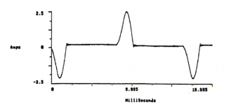
The haversine currents on the primary during high power delivery to the speakers will generate lots of harmonics, a cap could help dull those out a bit.
There's a nice illustration of haversine pulses in this link: https://www.sunpower-uk.com/glossary/what-is-haversine/
"The input current waveform of a power supply employing a capacitive filter will consist of haversine pulses which contain several harmonics."
Attachments
If your goal is to tame that, yes, why not. If your goal is to have clean DC output you can save that dollar.If you can tame this for a dollar, why not?
I thought the diodes were wired antiparallel.View attachment 1123876
I’m using 45A rated bridge with 450A pulse current. Two diodes in parallel will sustain 900A for full 16 ms. That will burn any fuse except nail.
Nice drawing. Now, if the power supply circuit accidentally faults hot to the internal zero volt line, the depiction guarantees that the chassis will not become hot as it is bonded to the ground back to the panel.
However, if the bridge opens during this fault, the zero volt line will climb to the hot potential. Now, the RCA shell is hot.
If the rca cord is connected to a double insulated UL approved device, it's shell would also become hot via the RCA.
If the second device is 3 prong, the mere act of trying to connect the two with the RCA cord would present the owner with a hand to hand potential.
This is why NEC says NO impedance in the bonding path.
NEC also says NEVER use just solder to complete a bonding connection, only listed devices. I would recommend a 25 or 35 amp bridge that uses 1/4 inch wide connectors that are crimped to the bonding wires.
I personally have seen copper leads to PC board solder fillets crack at the lead. This is due to the phase change shrinkage of solder, 15%, which puts the fillet into a shear/peeling force scenario.
John
- Status
- Not open for further replies.
- Home
- Member Areas
- The Lounge
- Power Conditioners and Cords