There's a nice illustration of haversine pulses in this link: https://www.sunpower-uk.com/glossary/what-is-haversine/
"The input current waveform of a power supply employing a capacitive filter will consist of haversine pulses which contain several harmonics."
Eh, no. This is how capacitor input current actually looks like. PS harmonics and primary current waveform are at post #183.
I thought the diodes were wired antiparallel.
You thought well. 🙂
They are, only in two antiparallel pairs.
Bryston brand power amps use a diode bridge between the signal ground and the chassis ground. They have done this for years.
Audioquest has a patent for putting a inductor in the ground path to reduce noise. Check it out.
https://patents.google.com/patent/US8988168B2/en
https://patents.google.com/patent/US8988168B2/en

Eh, no. This is how capacitor input current actually looks like.
I see that I attached the wrong image, which actually shows a typical non-linear current waveform in an SMPS.
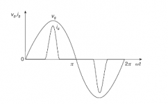
I now attach another diagram from my link that shows the relationship between the voltage and the unidirectional diode currents that flow during the conduction time. I think this is more in accord with your traces which I've also taken the liberty of attaching, but you can always say "Eh, no"! Nonetheless, the link remains explanatory.
I'm simply trying to explore the meaning of haversine waveform as introduced by jn. We're not all experts around here, and some of us are still trying to understand the mechanism by which power cords can make an audible improvement in hi-fi reproduction.
Attachments


I like your images that show the fast rising and falling current waveforms, this with the diodes and the transformers inductance causes RFI noise.
According to some of the reasoning being expressed here I must have a very dangerous external USB drive. The drive is powered by a wall wart. There is a USB cable that connects ground of the metal USB drive case the desktop PC case which could potentially become electrified if there were a loose ground somewhere. If there were to be a power fault at the PC then touching the external drive could result in a shock hazard. Come to think if it, I may also have a very dangerous cell phone that can connect to my computer via USB. It could happen. I have seen floating neutrals and even a wall socket where the ground connection became shorted to the AC line hot inside the wall of a building. Possibly even worse, I might have to drive a car which I know can result in a fatal accident not of my doing. Code requires I have a DL, registration, proof of insurance, and tires with at least 2/16" of tread depth for any two adjacent treads. I am compliant, but not safe.
Last edited:
Lots of filtering going on. Do note that it looks like all the green wires are ground, and they all appear to be screw connected, not soldered. Good practice.Look at all the inductors in the ground paths.View attachment 1123951
Are those coils the type that saturate hard? High inductance until high current is drawn, but low L with current? Are they dual winding common mode?
I recall bryston doesn't go for UL, but do the Canada CSA thing. I think the statement was "inspect at the level of", but not actual listing.
I make sure any fault will run the breaker in the magnetic regime. Not sure what that unit does without a schematic.
Without a clear schematic or understanding, just assuming that inductors can be allowed in the ground to break a loop can be a very dangerous thing.
John
A not very reasonable response to the discussion at hand.According to some of the reasoning being expressed here I must have a very dangerous external USB drive. The drive is powered by a wall wart. There is a USB cable that connects ground of the metal USB drive case the desktop PC case which could potentially become electrified if there were a loose ground somewhere. If there were to be a power fault at the PC then touching the external drive could result in a shock hazard. Come to think if it, I may also have a very dangerous cell phone that can connect to my computer via USB. It could happen. I have seen floating neutrals and even a wall socket where the ground connection became shorted to the AC line hot inside the wall of a building. Possibly even worse, I might have to drive a car which I know can result in a fatal accident not of my doing. Code requires I have a DL, registration, proof of insurance, and tires with at least 2/16" of tread depth for any two adjacent treads. I am compliant, but not safe.
I would prefer technical tidbits.
John
Your left jpg is the ideal haversine that would be seen on the AC legs of the bridge. It is odd order harmonics.I see that I attached the wrong image, which actually shows a typical non-linear current waveform in an SMPS.
I now attach another diagram from my link that shows the relationship between the voltage and the unidirectional diode currents that flow during the conduction time. I think this is more in accord with your traces which I've also taken the liberty of attaching, but you can always say "Eh, no"! Nonetheless, the link remains explanatory.
I'm simply trying to explore the meaning of haversine waveform as introduced by jn. We're not all experts around here, and some of us are still trying to understand the mechanism by which power cords can make an audible improvement in hi-fi reproduction.
At the capacitor, the current pulses will be even order harmonics. Layout and loop control in the chassis is very important to keep these odd and even harmonic rich pulses from attacking the ground reference for the circuits, as well as not allowing the fields to stray through loop on the circuit board.
One basic EMC/EMI principle is that of current control, where do current flow in the signal path?
Two boxes with simple bonding to ground back to the outlet tied by an RCA form the loop. Low frequency audio will not return to the source by the RCA shield, but rather by the ground. Once the ground loop impedance gets in the way of the frequency, then the RCA carries both send and return currents.
To top that off, an IEC filter will conduct noise from the hot conductor directly to ground via the filter cap. If you put too many of these filters on a GFI circuit for example, it can false trip the 6mA GFI must-trip threshold. But that ground current is part of the signal return path for the aforementioned equipment scenario. (love that word..aformentioned...
I've been using a Fluke 368 to check out grounding currents, not surprised to find 20, 30 milliamps of stray on the ground lines.. totally impossible to use on a GFI. We are beginning to implement GFI's throughout the building for users who bring their own equipment in, as we've been burned about 4 times in the last few years by faulty equipment as well as user modified.
I also use a Fluke 1630-2 to verify bonding integrity.
John
I like your images that show the fast rising and falling current waveforms, this with the diodes and the transformers inductance causes RFI noise.
It looks like a steep change but, considering that time base is 4 ms/div, it is actually slow change. As Mark Johnson explained in detail in his work published at Linear Audio and at Quasimodo thread, biggest dI/dT is at the moment rectifier stops conducting. At this moment ringing occurs. It is well visible at post #291. Resulting EMI is in RFI spectrum (167 kHz) but has low energy and doesn’t reach even first PS capacitor. I checked this as well in case of high quality 500VA toroidal transformer and ringing frequency was about 600 kHz. Again, nothing at all at PS output or amplifier circuit.
RFI noise could be picked up by small AM radio only up to 2-4 cm apart from wires, and that’s it.
It is important to point that rectifiers used were MOSFETs under LT4320 chip control. Results are at least 10x less ringing than with best diodes in Linear Audio article. Active rectifiers are in another league than diodes.
Also, EI transformers have more leakage inductance and will ring at lower frequencies than toroidal transformers.
BTW, Mark Johnson in literature section references your work: 🙂
[5] Miller, Rick (1994), “Measured RFI Differences Between Rectifier Diodes in Simple Capacitor-Input Power Supplies,” The Audio Amateur (magazine), Vol 1/1994, pp.26-27.
Last edited:
Did you look at the patent link I provided? It is about inductors in the ground path. In there might be answers to your questions, but maybe not. 🙂Lots of filtering going on. Do note that it looks like all the green wires are ground, and they all appear to be screw connected, not soldered. Good practice.
Are those coils the type that saturate hard? High inductance until high current is drawn, but low L with current? Are they dual winding common mode?
I recall bryston doesn't go for UL, but do the Canada CSA thing. I think the statement was "inspect at the level of", but not actual listing.
I make sure any fault will run the breaker in the magnetic regime. Not sure what that unit does without a schematic.
Without a clear schematic or understanding, just assuming that inductors can be allowed in the ground to break a loop can be a very dangerous thing.
John
Thanks for including that reference of my work in 1994! Thanks too for the info on the transformer inductance.It looks like a steep change but, considering that time base is 4 ms/div, it is actually slow change. As Mark Johnson explained in detail in his work published at Linear Audio and at Quasimodo thread, biggest dI/dT is at the moment rectifier stops conducting. At this moment ringing occurs. It is well visible at post #291. Resulting EMI is in RFI spectrum (167 kHz) but has low energy and doesn’t reach even first PS capacitor. I checked this as well in case of high quality 500VA toroidal transformer and ringing frequency was about 600 kHz. Again, nothing at all at PS output or amplifier circuit.
View attachment 1123983
RFI noise could be picked up by small AM radio only up to 2-4 cm apart from wires, and that’s it.
It is important to point that rectifiers used were MOSFETs under LT4320 chip control. Results are at least 10x less ringing than with best diodes in Linear Audio article. Active rectifiers are in another league than diodes.
Also, EI transformers have more leakage inductance and will ring at lower frequencies than toroidal transformers.
BTW, Mark Johns in literature section references your work: 🙂
[5] Miller, Rick (1994), “Measured RFI Differences Between Rectifier Diodes in Simple Capacitor-Input Power Supplies,” The Audio Amateur (magazine), Vol 1/1994, pp.26-27.
Without a clear schematic or understanding, just assuming that inductors can be allowed in the ground to break a loop can be a very dangerous thing.
Schurter has offered "ground choke" options in their filters for a while now. Not just for audio applications.
Schurter AC Filters
I think that a problem with a lot of filters is that they often connect a series pair of capacitors from line to neutral and connect the junction of the two to ground. In a test set-up, with really short leads, that gives more common mode filtering. In actual practice, neutral is connected to ground back at the breaker box, so that causes a problem. Of course, that depends on the frequency and the length of the ground connection. In any case, it often increases ground currents. A lot of filters specified for medical applications don't have this capacitor pair. Wonder why...
I started, but my eyes always glaze over with that lawyer/patentese text. It's almost worse than the verbage in the NEC.Did you look at the patent link I provided? It is about inductors in the ground path. In there might be answers to your questions, but maybe not. 🙂
I'll revisit when I get a chance.
John
Seven min with Garth explaining why power cords matter, Take a break and relax with this video from the big EU show.
- Status
- Not open for further replies.
- Home
- Member Areas
- The Lounge
- Power Conditioners and Cords