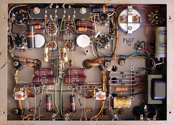
This is my first amplifier. RIAA phono preamp. I wasn't sure if it counted as point to point, but it looks like it does! This is shortly before I finished it. About the only thing I did after this was twist the remaining transformer leads.


There is a nice job of arranging the components and I don't know if the work is finished but several welds seem light to me.
I always try (as far as possible) to loop the legs of my components in the eyelets before soldering, the idea being that even if the solder is defective, the component is firmly hooked into its eyelet.
I always try (as far as possible) to loop the legs of my components in the eyelets before soldering, the idea being that even if the solder is defective, the component is firmly hooked into its eyelet.
I know exactly what you're talking about, and thank you for the constructive criticism. I'm aware of the "loop the component around the eye" school of thought, but given that this was my first dive, I wanted to maximize repairability and went with the "legs through and solder" school. I had to make use of that repairability a few times, and mostly due to poor solder joints. While I initially soldered the amplifier sections up in the chassis with all the turret strips bolted in, I eventually ended up unscrewing them from the chassis, and pulling the whole amplifier sections out like a big spider so I could get better access to some places. Specifically, I used the center posts of the turret strip (the one that bolts to the chassis) as the star ground point, but the leg, socket eye, screw, washers, nut, everything being grounded, and the chassis itself all ended up being a massive heat sink, and it was impossible to get enough heat into it to get a good solder joint. Up in the air with more than half the thermal mass removed, it was no problem. While I was there and had all that access, I went over every other single joint to make sure it was rock solid. The joints that look light only look light from the one angle. They look normal on the other side. Depends on what angles were available for the soldering iron, etc.
As for component layout, thank you for the compliment! I spent a lot of time laying everything out on paper in 1:1 scale. It took dozens of drafts over many evenings to get everything exactly where I wanted it with consideration to... everything I knew to consider. Then I redrew the component map at a large scale for easy reference while assembling. Even then, I ended up having to move two components on each channel in the moment due to an inability to gain comfortable access for the soldering iron, and I figured proximity to the heater wires wouldn't hurt if it were extended a little to boot.
As for component layout, thank you for the compliment! I spent a lot of time laying everything out on paper in 1:1 scale. It took dozens of drafts over many evenings to get everything exactly where I wanted it with consideration to... everything I knew to consider. Then I redrew the component map at a large scale for easy reference while assembling. Even then, I ended up having to move two components on each channel in the moment due to an inability to gain comfortable access for the soldering iron, and I figured proximity to the heater wires wouldn't hurt if it were extended a little to boot.

That's essential for critical road-trip equipment. Military Jeeps, country music bands in the Ozark Hills, even my mini-van from home to town over PotHole Road. I had recording gear that was thrown in backpacks and on hand-trucks a hundred times a year for a decade.loop the legs of my components in the eyelets
Pete Traynor used to throw stage amplifiers out the upstairs factory window. (He rented a lot, and he already knew how rented gear gets treated.)
In Mr 6000's situation, mostly not moving, not a paying job, and never far from the soldering iron, it can be a secondary concern.
A great history about Yorkville, Long, Mcquade, and Traynor can be read here: https://www.yorkville.com/downloads/other/yorkvillehistory.pdf
"Previously Pete had demonstrated the YBA-3’s ruggedness by throwing one out a
second-story window onto the street below. He then brought it back upstairs, shook out
the broken glass, replaced the tubes, plugged it into a cabinet and it worked perfectly, a
scenario that Steve Miller talked about for years afterwards"
I exactly do understand what you're saying. I've parted out amplifiers from old and wothless Hammond organs to save the tube sockets, which are of similar decent quality as yours', the 'iron' and the turret boards. It's always a PITA to clean the component wirtes from the solder lugs...I'm aware of the "loop the component around the eye" school of thought, but given that this was my first dive, I wanted to maximize repairability and went with the "legs through and solder" school.
Best regards!
Marantz 8B is still the best example of P2P wiring from the vintage land.
All my stuff is point to point. I escaped from the lab before home grown PCs were common or non-existent.
To me it never made sense to spend time of designing & making a PC for a One-Of Amp.
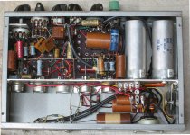
So the 33 Amp is PP 33s in triode or UL. Driven by another 33 triode connected thru a Hammond IT.
The front end is a 1B5/25S, it is somewhat microphonic.
The next is a very low noise cascode preamp for a mag phono pickup, Built circa 1956.
The last is PP 6V6s in Class AB2. The driver by a 6BQ7 CF, The front end is a PP Cascode, 6BQ7 on the bottom,
4BQ7 on the top. The 4BQ7 uses the 5V heater wdg on the PT, no H-K problems. 👍
To me it never made sense to spend time of designing & making a PC for a One-Of Amp.
So the 33 Amp is PP 33s in triode or UL. Driven by another 33 triode connected thru a Hammond IT.
The front end is a 1B5/25S, it is somewhat microphonic.
The next is a very low noise cascode preamp for a mag phono pickup, Built circa 1956.
The last is PP 6V6s in Class AB2. The driver by a 6BQ7 CF, The front end is a PP Cascode, 6BQ7 on the bottom,
4BQ7 on the top. The 4BQ7 uses the 5V heater wdg on the PT, no H-K problems. 👍
Attachments
So your saying you want to build your new unit with "classic" point to point wiring, be careful what you wish for....
Harmon Kardon TA-7000A receiver...
-----------------------------------------------------------------------------Rick....
Mozart would have said: "Too many notes!"
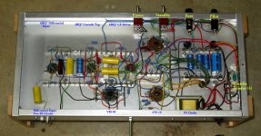
HAHA Ya. Mine is on the spaghetti end of it I think compared to the stuff above... But there's line, buffer, phono, 35W triode output, bluetooth, VU meters 6 way relay switch etc all built into the same box minus PSU.
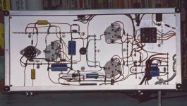
The top side for those who might care:
I miss the density: I can't get that with PCBs - point to point wiring is inherently three dimensional... This has been decommissioned.

The top side for those who might care:
I miss the density: I can't get that with PCBs - point to point wiring is inherently three dimensional... This has been decommissioned.
Well, there's point to point wiring and point to point wiring...It has nothing to do with the method itself, but with the execution.
Btw, forget those TEK ceramic strips. They weren't made for twist and solder joints. And thats the problem, soundwise.
But it could be kind of an art, though.
That must be the Mr Monk version.
What, no bass and treble controls? Not enough room for one or two more tubes? 😀HAHA Ya. Mine is on the spaghetti end of it I think compared to the stuff above... But there's line, buffer, phono, 35W triode output, bluetooth, VU meters 6 way relay switch etc all built into the same box minus PSU.
The top side for those who might care:
I miss the density: I can't get that with PCBs - point to point wiring is inherently three dimensional... This has been decommissioned.
View attachment 1122180
HAHA Ya. Mine is on the spaghetti end of it I think compared to the stuff above... But there's line, buffer, phono, 35W triode output, bluetooth, VU meters 6 way relay switch etc all built into the same box minus PSU.
The top side for those who might care:
I miss the density: I can't get that with PCBs - point to point wiring is inherently three dimensional... This has been decommissioned.
View attachment 1122180
It’s a bird, it’s a plane, it’s a rocket, it’s…superman riding a Christmas tree!
I tried that once but decided a proper 31 band EQ was better 🙂 It's bypassed 99.9% of the time though so it seems like a waste.What, no bass and treble controls? Not enough room for one or two more tubes? 😀
At least it didn't catch fire LMAOIt’s a bird, it’s a plane, it’s a rocket, it’s…superman riding a Christmas tree!
- Home
- Amplifiers
- Tubes / Valves
- Point to point wiring