No joke, people have used MOSFETs for the JLH69. Dubious, I've not tried it. MOSFETS may be more linear than BJTs, and while they have a sweet spot where the drain current is stable with gate voltage over temperature, this is usually at a moderately high current level. Careful choice of MOSFET may yield a workable design, but there are so many FETs out there and several which have gone obsolete already it makes choosing a challenge.use MOSFETs for JLH69 topology?
it's a joke?
Maybe some DIY-ers have experience of the thermal stability of MOSFET JLH's. Possibly a modification using a thermal compensation technique in the drive current source (more like an updated 69) has been used?
What are you talking about right now?No joke, people have used MOSFETs for the JLH69. Dubious, I've not tried it. MOSFETS may be more linear than BJTs, and while they have a sweet spot where the drain current is stable with gate voltage over temperature, this is usually at a moderately high current level.
Have you seen the topology? with mosfets, you don’t even have to remember about any linearity, it will work and all right ... Why do you need such a "moped"?
Not sure what you refer to now. Your previous comment suggested you thought using MOSFETs in a JLH69 was a joke.
All I mentioned was that they have been done, so now are you saying they're not a joke?
I think the cross-conduction which may occur with a fast square wave is dangerous, when both output devices are on. That occurs when all the output devices are as fast as the driver, and happened way back in TTL logic gates, which the JLH69 is similar to. A better circuit would be a complementary output stage, I suggest, but could still operate in Class A.
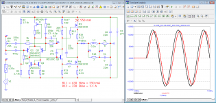
If you don't need a very high current value, I recommend 2sc4793 for driver stateSpeaking of building, I found a pair of tiny, 5 x 5 cm PCBs for a hexfet version of JLH'69 - forgotten in my stack of things to do. The boards are marked for IRF250 power mosfets but surely that means IRFP250 as they have linear spacings for TO3P, TO247, 264 etc. style pinouts. A number of old IRFP types have been particularly cheap from China over recent years and that's great but surely there are others, perhaps better suited to 10-15W of class A audio. I don't fancy TIP41C which is marked for the driver/splitter either. Any better suggestions for that role too?
Or, maybe you are referring to my comment about temperature stability. For that you need to look at the datasheets of MOSFETs, where the drain current and gate voltage are shown as a function of temperature. In the JLH69 there is no mechanism for controlling the bias current other than the gain of the output devices. For MOSFETs that may not be a good idea, since the transimpedance is high and at lower gate voltages, the drain current has a PTC, only going to NTC at higher currents.What are you talking about right now?
Have you seen the topology? with mosfets, you don’t even have to remember about any linearity, it will work and all right ... Why do you need such a "moped"?
In the JLH amplifier, the entire collector output current of the stage driver flows into the base (is the control)Or, maybe you are referring to my comment about temperature stability....
for the output power transistor.
Where will the current flow with Mosfet?
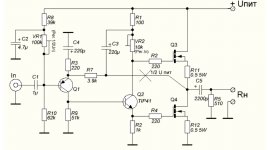
Apparently not. I found a link to similar, if not the same boards at a popular Chinese platform site. They were finished and fitted with the marked mosfet types but the included schematic is incorrect since it shows only BJT transistors. Another interesting feature is the claim that it requires only 10-50 mA bias current! That should make some eyes roll......use MOSFETs for JLH69 topology?
it's a joke?
https://www.aliexpress.com/item/4000538304554.html?spm=a2g0o.productlist.0.0.28d04d6b3Bu2BD&algo_pvid=dea8d6e4-1fd5-4b74-9a56-024b5ca8490e&algo_exp_id=dea8d6e4-1fd5-4b74-9a56-024b5ca8490e-51&pdp_ext_f={"sku_id":"10000002761025944"}&pdp_npi=2@dis!AUD!32.82!24.29!!!!!@2101e9cf16710312668714105e728e!10000002761025944!sea&curPageLogUid=p0a19WK3FrFC
Chinese
Attachments
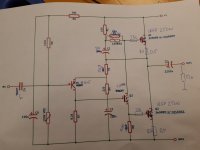
As OldDIY has posted, there are several variants out there with MOSFET outputs.
The "current" you are concerned about, which is important in the original BJT version, is less obvious in the MOSFET design. MOSFETs at low frequencies are voltage driven, and so it's the voltage across the gate which varies. The middle circuit oldDIY shows is typical, I have not investigated it, but the voltages of concern would be the lower gate resistor R2 and the variable resistor in the collector of the driver. If they are not equal, the FETs will not conduct balanced currents. So this concept is pretty poor. I would have at least added a similar value resistor to R2 in the upper MOSFET gate to source, so that the voltages stand a chance of balancing, but with fast MOSFETs, they could both turn on hard in a fast transient. Plus, the high transconductances available today means that the bias current in the devices is quite critical and whatever value the bootstrapped resistor ends up could still be unbalanced to the lower resistor.
(And before others chip in, yes the gate capacitance of MOSFETs needs current to charge. So a symmetrical AC performance needs equial impedances for HF operation, and yes, then the current into the gate becomes significant).
So I make my case that it would be far better to use a complementary output pair with a bias regulator FET but to maximise output power the driver and its emitter connection may have to be to higher voltage rails.
Thanks John Ellis, for that synopsis. As suspected, there are some fundamental problems. We also need to make our own component choices and connect to some arbitrary power supply and speakers before anything good happens, so there will probably be more to deal with than imagined.
As far as a visual scan of the tracks and marked component values can tell, the second schematic posted at #8628 by Old DIY (thanks again) is close, if not the same as the boards I have and also the linked images posted at #8627. I should add that I consider this a novelty project that costs very little so I might just build one of these boards and see if anything smokes or silently dies before I can see much on the oscilloscope. Naturally, I'm curious to hear if there's really any of that JLH magic sound quality that we all hope to hear.
As far as a visual scan of the tracks and marked component values can tell, the second schematic posted at #8628 by Old DIY (thanks again) is close, if not the same as the boards I have and also the linked images posted at #8627. I should add that I consider this a novelty project that costs very little so I might just build one of these boards and see if anything smokes or silently dies before I can see much on the oscilloscope. Naturally, I'm curious to hear if there's really any of that JLH magic sound quality that we all hope to hear.
Last edited:
The difficulty lies in the choice of real MOSFETs suitable for linear amplification at currents less than 1A. We see the optimization of devices for fast switching of high currents (50-100-200A). The TO-220 package is widely used. The pulsed power increases and the DC power decreases (bad for class A). The recommendations that I have seen suggest the use of devices with low switching current (12-30A), with the lowest possible junction capacitance in TO-264, TO-247 cases. For power, it is preferable to use regulated power supplies.
During transients, through currents may be present. Rescued by low-resistance resistors in the source and the overload capacity of the MOSFET.
Kit sellers suggest setting a quiescent current of 40-90 mA (class AB).
During transients, through currents may be present. Rescued by low-resistance resistors in the source and the overload capacity of the MOSFET.
Kit sellers suggest setting a quiescent current of 40-90 mA (class AB).
Last edited:
My experience: the quality of sound of parts does result of "exact" "current", "flow": the form, materials, diameters... are crucial for sound (cleanness, clearness, "musical flow"...
If bjt, mosfet, jfet, frequency response, bias, gain... they are much less necessary:
thus: test, try everything you can get;-)
If bjt, mosfet, jfet, frequency response, bias, gain... they are much less necessary:
thus: test, try everything you can get;-)
Last edited:
he "current" you are concerned about, which is important in the original BJT version, is less obvious in the MOSFET design.
MOSFETs at low frequencies are voltage driven, and so it's the voltage across the gate which varies. The middle circuit oldDIY shows is typical, I have not investigated it, but the voltages of concern would be the lower gate resistor R2 and the variable resistor in the collector of the driver. If they are not equal, the FETs will not conduct balanced currents. So this concept is pretty poor.
These two sentences of yours are contradictory. Of course I mean the meaning of the second sentence.
Well, you did not explain what current you were talking about. At low frequencies, the current into the gate of a MOSFET is very low, so the circuits shown work, albeit not ideally, as I have explained. So if you meant at high frequencies when the gate current is really needed, that is, I agree, where the MOSFET circuit has a problem. But that isn't really much different from a BJT situation at the end of the day, because the frequency response falls (-3dB at fhfe) and so to push a BJT faster, you still need more current than the JLH driver could supply. That's why I've been keen to suggest using the faster output devices available today, so you get a higher bandwidth wtihout loading the driver beyond it's D.C. capability.These two sentences of yours are contradictory. Of course I mean the meaning of the second sentence.
Though I should also add that the input capacitances of modern BJT devices is also high, which may need more current, once more, for high frequency response. And without symmetrical driver transistors, sucking current out of the base is more difficult for the lower output transistor in the original JLH with just a 2k resistor or thereabouts to do it.
I guess we won't be able to come to a definitive conclusion until we try and do it. A lot of things in audio circuits often go beyond math and electronics. For example, there are very few audiophiles who don't like the sound of a distortion machine tube amp.
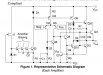
Does this microcircuit not remind us of anything? It means you need to collect JLH that way.🤔
https://www.onsemi.com/pdf/datasheet/mc33078-d.pdf
https://www.onsemi.com/pdf/datasheet/mc33078-d.pdf
Attachments
Last edited:

Collect or connect? In any case I'm not sure I would have considered op-amp design as a guideline for power amps. I guess that derives from formal training.
Last edited:
To develop in the same way and check in the simulator. The output cascade is similar to JLH.Collect or connect?
- Home
- Amplifiers
- Solid State
- JLH 10 Watt class A amplifier