Hello. Please what is the power, Watts or VA of the toroid transformer? I ' m sourcing toroid and PSU for my JLH 2003. The case is a Modushop 300mm 4U. Thanks.Attached is a picture of the JLH amp I built some time back. It has since been modified - I removed the soft start board (left rear), "Ground Lift" (Right Rear) and the twin PSU's (Centre front). The twin PSU has been replaced by one of Bonsai's Ripple Eaters which feeds both amps.
The output trannies are mounted on Aluminium 'L' brackets on both sides. The 'L' bracket is positioned roughly 1/3 from the bottom of the heatsinks.
The two output transistors are equally spaced on each bracket.
The case is a Modushop 2U. With ± 15V DC supply and 1.5 Amp bias, the heatsinks run at around 30°C above ambient.
Hope this helps.
Your example:Hello. Please what is the power, Watts or VA of the toroid transformer? I ' m sourcing toroid and PSU for my JLH 2003. The case is a Modushop 300mm 4U. Thanks.
2 x 15 V = 30 V.
30 V x 1,5 A = 45 VA.
2 x 45 VA = 90 VA.
For continuous load, power should transformers load be at least double: 2 x 90 VA = 180 VA. Minimum;-)

@cumbbA JLH-power-follower balanced. Without any separate differential-amp or others;-) "Self-balancing"-)
How does THAT sound;-?
;-)))))))))))))))))))))))))))))))))))))))))))))))))))))

I am trying to wrap my head around this one, but admit that I am struggeling🙂 Appreciate if Sensei could provide some beating with the stick.
Start by defining V+... Perhaps 24V?@cumbb
I am trying to wrap my head around this one, but admit that I am struggeling🙂 Appreciate if Sensei could provide some beating with the stick.
View attachment 1124312
Helo cumbbYour example:
2 x 15 V = 30 V.
30 V x 1,5 A = 45 VA.
2 x 45 VA = 90 VA.
For continuous load, power should transformers load be at least double: 2 x 90 VA = 180 VA. Minimum;-)
Are this 180VA minimum for one channel? TIA
VA ratings depend on the source of the transformer. Chinese DIY transformers may only be rated for PEAK power - a poorly defined quantity which is understood from online store advertising, to be 2 x the CONTINUOUS power rating that most people here will be familiar with. Generally, just compare the physical dimensions and mass of the transformer with an equivalent rating European, US etc. product. For class A amplifiers, there is no point in calculating with anything but the CONTINUOUS power rating.
From the above post and #8642, it should be clear that 2 x 45VA = 90VA means exactly that - a continuous load of 90VA for both channels together. Increasing the rating may allow the transformer to run cooler and longer if you use the amp. a lot but it also means a wider radiated noise field. Sometimes a special type of nickel-iron cover over the transformer, as copied in steel on some finished JLH69 products and other high quality amps, can help there.
From the above post and #8642, it should be clear that 2 x 45VA = 90VA means exactly that - a continuous load of 90VA for both channels together. Increasing the rating may allow the transformer to run cooler and longer if you use the amp. a lot but it also means a wider radiated noise field. Sometimes a special type of nickel-iron cover over the transformer, as copied in steel on some finished JLH69 products and other high quality amps, can help there.
Last edited:
I hope, I do remember right:@cumbb
I am trying to wrap my head around this one, but admit that I am struggeling🙂 Appreciate if Sensei could provide some beating with the stick.
View attachment 1124312
1.: Set the/one (unbalanced) input at base of T2 (of one circuit).
2.: Connect the bases of T3 (of both circuits) - per cap.
But: the signal of one follower "sees", will be modulated by noise and character of, one transistor, the signal of the other follower will "see", will be modulated by noise and character of, four transistors: no pure balancing - once disregarding the entire circuit, not including all conceivable influences.
I would prefer a transformer to balance the source-signal.
12 V and max. 1 A? I just have an accu in mind. Leave out the capacitors. Do not use any that bridge the accu. That's how I would test it finally.
For max sound too: do not paralleling different resistors: e.g. 2,2k and trimmer. And: do use two pins of the trimmer only - leave the third.
BD139 could run very well;-) Just try;-) All BD139 I had tested had sound very good, with own character - like pure and outstanding beer or wine;-)))
https://insel-brauerei.de/en/navigation/28a1d2bccdb54a73a801c77c25cd61fb
Last edited:
Three transes and one cap. Sorry, was midnight, and artificial electromagnetic fields of e.g. computer and monitor, and of mobile radio (THE key technology of the New World Order) of the neighbors (WLAN, Bluetooth, mobile...) makes me slide into dementia and exhaustion: digital life will probably put an end to us analog life;-)"the signal of the other follower will "see", will be modulated by noise and character of, four transistors"
What is this supposed to achieve?@cumbb
I am trying to wrap my head around this one, but admit that I am struggeling🙂 Appreciate if Sensei could provide some beating with the stick.
View attachment 1124312
The output centre rail(s) is (are) undefined. The input transistor(s) need a bias of some sort, and the simplest is a negative feedback from the output rail to the base, either as a single resistor (very dependent on the gain of the transistor, so will need to be potentiometer + resistor combo) or as a potential divider (better, but reduces the overall gain due to increased NFB, but also distortion improved).
Define the output required, then that should lead to the supply voltage, and we can work from there.
As the circuits stand, the outputs will stick at a voltage just below the supply.
The purpose was merely to try to figure out a working circuit based on Mr. cumbbs previously posted photos. Since its a bit off topic, I started a separate thread here: https://www.diyaudio.com/community/threads/cumbbs-koans.393926/What is this supposed to achieve?
The output centre rail(s) is (are) undefined. The input transistor(s) need a bias of some sort, and the simplest is a negative feedback from the output rail to the base, either as a single resistor (very dependent on the gain of the transistor, so will need to be potentiometer + resistor combo) or as a potential divider (better, but reduces the overall gain due to increased NFB, but also distortion improved).
Define the output required, then that should lead to the supply voltage, and we can work from there.
As the circuits stand, the outputs will stick at a voltage just below the supply.
Sorry, just came across this question today.Hello. Please what is the power, Watts or VA of the toroid transformer? I ' m sourcing toroid and PSU for my JLH 2003. The case is a Modushop 300mm 4U. Thanks.
I'm using the Modushop 2U chassis and use a 15V/160VA transformer. The bias current was set at 1.5A because otherwise the heat sinks get too hot for my liking (they currently run ± 35 °C above ambient).
The PCB was, at the time, a free offer from a company called "Siliconray' (from memory - the dual rail version of the original - 2005, 15W)
The Modushop 4U would be a much better fit, I think, for this amp and will allow you to run higher bias currents/increase power output with a larger transformer.
Originally the amp suffered quite a lot of hum with a simple PSU so I changed the original out for a single 'Ripple Eater' and now the hum is negligible - so I would suggest this approach.
the worst and most unstable of all the JLHs I've had, I still have the populated boards somewhere on a shelf.Sorry, just came across this question today.
I'm using the Modushop 2U chassis and use a 15V/160VA transformer. The bias current was set at 1.5A because otherwise the heat sinks get too hot for my liking (they currently run ± 35 °C above ambient).
The PCB was, at the time, a free offer from a company called "Siliconray' (from memory - the dual rail version of the original - 2005, 15W)
The Modushop 4U would be a much better fit, I think, for this amp and will allow you to run higher bias currents/increase power output with a larger transformer.
Originally the amp suffered quite a lot of hum with a simple PSU so I changed the original out for a single 'Ripple Eater' and now the hum is negligible - so I would suggest this approach.
I'm curious how many of this series is still in operation.
I had everything with this one, ahem, hiss, oscillation, destruction of output devices + suicide speakers.
I remember a member here managed to make them stable and functional but ended up reverting to an older version.
Apart from using too small a chassis for full output, the other problem I had was with the driver transistor which got very hot. There's insufficient room to add anything but a 'stick-on' heatsink. The high temperature of the driver was another reason I set the bias low.the worst and most unstable of all the JLHs I've had, I still have the populated boards somewhere on a shelf.
I'm curious how many of this series is still in operation.
I had everything with this one, ahem, hiss, oscillation, destruction of output devices + suicide speakers.
I remember a member here managed to make them stable and functional but ended up reverting to an older version.
Somewhere in the distant past I think there may have been a suggestion the driver should also be mounted on the heatsink between the output transistors?
The PCB quality seemed fine but the component layout, not so much.
Anyway, apart form the hum I had checked both amps out on my 'scope' and had found nothing untoward. I don't use the amp often these days but when I do, it still sounds a very sweet amp, especially at the high frequencies.
it must be ten years ago, I don't remember exactly the setbacks, I just remember that it was the last amp that I didn't test on the table before putting it in its final box and that it was a good lesson.Apart from using too small a chassis for full output, the other problem I had was with the driver transistor which got very hot. There's insufficient room to add anything but a 'stick-on' heatsink. The high temperature of the driver was another reason I set the bias low.
Somewhere in the distant past I think there may have been a suggestion the driver should also be mounted on the heatsink between the output transistors?
The PCB quality seemed fine but the component layout, not so much.
Anyway, apart form the hum I had checked both amps out on my 'scope' and had found nothing untoward. I don't use the amp often these days but when I do, it still sounds a very sweet amp, especially at the high frequencies.
I never understood what siliconray wanted to do and where he was going with his offer and he quickly disappeared leaving dozens of people on the side of the road with defective amps.
I think the amp, being a well known and regarded design was supposed to be a great intro for his company, particularly as a free offer. Sadly it didn't pan out. Perhaps the component selection was very critical, and/or the actual placement of the amp within the chassis might have caused some to have difficulties and I was just one of the lucky ones. If something does go wrong eventually, perhaps I'll look at an alternative set of PCBsit must be ten years ago, I don't remember exactly the setbacks, I just remember that it was the last amp that I didn't test on the table before putting it in its final box and that it was a good lesson.
I never understood what siliconray wanted to do and where he was going with his offer and he quickly disappeared leaving dozens of people on the side of the road with defective amps.
Yeah, chances are it's a mix of all of these.I think the amp, being a well known and regarded design was supposed to be a great intro for his company, particularly as a free offer. Sadly it didn't pan out. Perhaps the component selection was very critical, and/or the actual placement of the amp within the chassis might have caused some to have difficulties and I was just one of the lucky ones. If something does go wrong eventually, perhaps I'll look at an alternative set of PCBs
I assembled all the JLHs and it's the only one that gave me a problem and yet I have enough components in stock to open a store.
My favorites are the 69 and the 96, I don't need a lot of power and have a few 8 and 16 ohm speakers.
The 69 (in its simplest version) with a power supply in 𝝅 and the only one that has been in operation at my house for years.
https://www.diyaudio.com/community/threads/free-jlh-hifi-headphone-amp-pcb-0-008-thd.202614/The PCB was, at the time, a free offer from a company called "Siliconray'
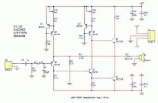
...dual 9V toroid transformer
...This is a headphone, not speaker amplifier.
They work on +-12V.
...#33 I have now modified this circuit for a higher current...
All I did was add 4 more pairs of output devices and juggle a few resistor values.
In this example I have the bias set at 3 amps per device so each one is dissipating 36 watts approximately half of what an MJE3055 can do.
...#81 I'm still not convinced about some of the ground plane solder joints which are an absolute pain on these boards. Anyway, I've used the meter and it tells me I have continuity and no unexpected resistances so I've started to install the boards with a view to powering them up.
Last edited:
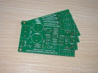
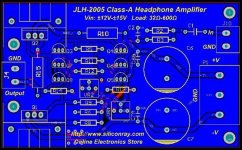
Nope the one below:https://www.diyaudio.com/community/threads/free-jlh-hifi-headphone-amp-pcb-0-008-thd.202614/
...dual 9V toroid transformer
...This is a headphone, not speaker amplifier.
They work on +-12V.
...#33 I have now modified this circuit for a higher current...
All I did was add 4 more pairs of output devices and juggle a few resistor values.
In this example I have the bias set at 3 amps per device so each one is dissipating 36 watts approximately half of what an MJE3055 can do.
...#81 I'm still not convinced about some of the ground plane solder joints which are an absolute pain on these boards. Anyway, I've used the meter and it tells me I have continuity and no unexpected resistances so I've started to install the boards with a view to powering them up.
https://www.diyaudio.com/community/threads/free-pcb-for-jlh-2005-class-a-amplifier.200659/
- Home
- Amplifiers
- Solid State
- JLH 10 Watt class A amplifier