The bias current originally suggested was 1A for each channel, which assumed the single supply voltage was no more than ~30VDC, presumably because that's for a nominal10W output from BJT semis and 8R speakers - mosfets being out of contention in 1969. Perhaps a bit more current is necessary for mosfets in class A. Obviously, the more power output demanded, the more bias current will also be needed.
Read the original magazine article which includes tables for various supply voltages, speaker impedances etc. for at least BJTs. The website is well known as The Class A Amplifier Site, now hosted by Rod Elliott as an archive at https://www.sound-au.com/. Check the index page for that title and click on it to link to the archive of several articles and more recent projects.
Read the original magazine article which includes tables for various supply voltages, speaker impedances etc. for at least BJTs. The website is well known as The Class A Amplifier Site, now hosted by Rod Elliott as an archive at https://www.sound-au.com/. Check the index page for that title and click on it to link to the archive of several articles and more recent projects.
Last edited:

This is an early US patent not related to Hood. Amplifier (repeater) of a telephone line on 4 BJT. The circuit is distinguished by the absence of a bootstrap and a resistor with a capacitor from the emitter of the first transistor to ground 🙂is this the patent for the JLH 69 circuit?
I should have researched more of what's currently available in finished form, from China. There is, apparently, a lateral mosfet JLH version from Breeze HI-FI who may be just one of several sellers. I can't accept that its mosfets are branded TOSHIBA but also marked J162, which is a Renesas part number, though. As usual, there's something misleading about their promotional blurb but I wonder what's really inside and how the finished product sounds...?? A friend has one on order so I hope to hear for myself when it arrives. https://www.aliexpress.com/item/1005005050098088.html?"You will see similar types of fakes and fake logos among the various versions of Hitachi 2SB649,D669,B647,D667 for example.
Hello all,
I would be most grateful for some help with my JLH 1969 hum.
Having watched Steve Wagner's instrument test of this board I decided to make one myself.
This is it on what has become my test bed

And here is Steve's drawing of the board and the circuit.

I switched on to check the 1/2 at 14.5 volts that was OK the quiescent current is set at 1.2 Amps and I am using an FH3 with the 4ohm CHP-70 original.
With and without an input the hum becomes louder as I turn the pot up and sounds like mains hum. I've taken the ground from the input and from the pot, the input, and the front panel to the star and from there to the earth on the IEC connector. All the ground connections on the board are connected to each other.
I do hope someone can see what I have done wrong from looking at the pics.
Cheers - J
I would be most grateful for some help with my JLH 1969 hum.
Having watched Steve Wagner's instrument test of this board I decided to make one myself.
This is it on what has become my test bed
And here is Steve's drawing of the board and the circuit.
I switched on to check the 1/2 at 14.5 volts that was OK the quiescent current is set at 1.2 Amps and I am using an FH3 with the 4ohm CHP-70 original.
With and without an input the hum becomes louder as I turn the pot up and sounds like mains hum. I've taken the ground from the input and from the pot, the input, and the front panel to the star and from there to the earth on the IEC connector. All the ground connections on the board are connected to each other.
I do hope someone can see what I have done wrong from looking at the pics.
Cheers - J
I think this is good info:
https://hifisonix.com/wp-content/uploads/2019/02/Ground-Loops.pdf
Measure DC input with your multimeter set to AC, you might have high PSU ripple
https://hifisonix.com/wp-content/uploads/2019/02/Ground-Loops.pdf
Measure DC input with your multimeter set to AC, you might have high PSU ripple
Last edited:
BJTs suffer when they switch.
Class A operation removes the main advantages that lateral mosfets have.
The much higher Vgs vs Vbe will limit swing a lot in this circuiy
Class A operation removes the main advantages that lateral mosfets have.
The much higher Vgs vs Vbe will limit swing a lot in this circuiy
Hello,
Progress report, thank you all for your input I did not expect so much so soon.
What I've done so far, ditched the power supply and replaced it with one 10k uF capacitor, connected the star to the power ground and in turn to the Earth by the little black box which is an RFI filter.
The hum diminished, I turned the pot up with no input connected expecting the hum to get louder it did not, once passed a certain point the hum stopped! Sticking my ear'ole to the speaker cone all I could hear was a faint hum. Hmmmm I thought old pots (not the railway out of Shrewsbury) might be the problem. When I get time I'll replace the pot, well, you never know.
Cheers and thanks- J
Despite the hum I had a listen, the person who said you don't need to make a JLH type audio comparison to see what Class A means, my single speaker came alive.
Last edited:
That sounds a little worrying. If the input impedance changes the hum it suggests that your amplifier might be oscillating. The frequency response of the input stage will be affected by an impedance, and normally a low impedance (volme at zero) should give no or minimal hum. But that also would give the highest frequency response and it could be that the oscillations are causing excess ripple on the power line. I note that you have NJW0281's which may require small frequency compensation capacitors to stop oscillation.
Are there any power line decoupling capacitors on the PCB? I don't see any, and your leads from the PSU PCB could be jsut long enough to generate unwanted inductance. Especially with HF transistors I would have put something like 100uF-1mF on the PCB next to the collector of the upper output transitor to ground.
Also twist the output lead pair, and the power supply feed pair to keep the inductance formed from rather haphazard loops low.
Do you have an oscilloscope or could you borrow one from somewhere?
Hello John,
Nice of you to make a comment and with such comprehensive advice. The output transistors in my kit are 2SD1047. I think C2 on the diagram is a decoupling one. I do have a Oscilloscope a little plastic one that I assembled from a kit to check the output from some oscillators I made it's a DSO138 from Aliexpress. I will have a go at twisting some wires if the new pot does nothing. and report back soon.
Mr Wagner is in the USA his kit with the NJW0281's came in a box, his YT instrument test of the kit can be seen here, apologies I should have put that in my original post
Cheers - J
You are probably having difficulty with only having a couple of sides of chassis and hence lacking proper earth shielding, if your pic shows what you have actually been listening to. That testbed assembly shown in #8684 may be OK for functionality checks but most probably misleading as an indicator of audio problems, other than it is likely a problem. Eventually, you'll have to build the amplifier in a "full metal jacket" if you expect to compare or simply enjoy using audio gear to the full, low noise extent. Save up the pennies and start right from the outset. It's much quicker and more satisfying than having to grind through the hard lessons, back and forth, time and again.
Last edited:
Your transistors are isolated from the heatsink. But the heatsink itself is not grounded. This could be a source of interference.
The 2SD1047 is perhaps not quite as fast as NJW0281 but still a "fast" type, so might have the problem of oscillation.
Does your scope have a frequency response of say 10MHz? Oscillation frequencies tend to be in the range 1-5MHz or so if they occur, but could be higher. Check the input voltage rating of your scope and use coupling capacitors which are grounded through moderate resistances (e.g.10k) as signal take-offs if you need to keep DC levels low.
Other comments I'd agree with are to connect all your metalwork to ground properly, either assembling a complete chassis or hardwiring with an earth lead, and using screened cable on the volume pots.
The ungrounded metal parts may well be picking up hum but I'd still suspect oscillation if the volume pot is turned to zero and the hum hasn't gone, and disappears at higher settings. With a Class A circuit like this it seems oscillation won't change the static current by much compared to a Class AB design.
Capacitor C2 will only decouple the power line to the input stage. High frequency power transistors need capacitors to ground locally - next to them - to minimise inductance effects in the lead wires. That is what I suggest is needed. I'd have put another 3.3mF cap on the PCB if I'd laid it out. Needs to have its own path to the PSU negative (common earth point) but should be able to share with the negative power lead.
Hello all,
I must thank you all again for your excellent advice, very well done indeed.

From the top down, the star is now only for the metal panel/heatsink ground and straight to the mains Earth wire
I found some old shielded wire studio flash firing cable and used that to the pot and from the pot to the board, I've ordered some more but in 3.0mm diameter.
The ground connection is from the power return and to the mains Earth from the Negative pin of the bridge rectifier.
I halved the input voltage to from 24 Volts to 12 Volts just to see if it would work, with the odd result that the volume rises much faster than it did with 24 Volts.
My speakers are FH3's with CHP-70 4 Ohm originals and are rated at 85 db.
Ohh and the hum, back to sticking ones ear'ole right up against the speaker cone to hear a minute hum.
I will be doing my switched test with the JLH and my 3886, I'll let you know the result.

This is the cable I used to switch the inputs from one amp to the other
Cheers - J
I must thank you all again for your excellent advice, very well done indeed.
From the top down, the star is now only for the metal panel/heatsink ground and straight to the mains Earth wire
I found some old shielded wire studio flash firing cable and used that to the pot and from the pot to the board, I've ordered some more but in 3.0mm diameter.
The ground connection is from the power return and to the mains Earth from the Negative pin of the bridge rectifier.
I halved the input voltage to from 24 Volts to 12 Volts just to see if it would work, with the odd result that the volume rises much faster than it did with 24 Volts.
My speakers are FH3's with CHP-70 4 Ohm originals and are rated at 85 db.
Ohh and the hum, back to sticking ones ear'ole right up against the speaker cone to hear a minute hum.
I will be doing my switched test with the JLH and my 3886, I'll let you know the result.
This is the cable I used to switch the inputs from one amp to the other
Cheers - J
Last edited:
That's plain, insulated wire. Unless some ever-present hum and/or noise level in your audio is OK, all audio signal connections over any distance between the board and controls, in/out connectors etc. are best made with grounded, shielded cable - the shorter the run and the further from AC power wiring and transformer, the better. Sometimes, you can also cause hum loops this way when you couple ground between circuits multiple times but unless you have specific advice about connections to your gear, its simpler to begin with using the cable. Its not hard to disconnect the braided shield wire at one end if it causes a definite problem.
If you are looking for suitable cable, most homes will already have an unused stereo connector lead or even an AV lead that likely contains suitable shielded wire. Why buy new and over-priced bits and pieces when you already have suitable materials lying unused, in a drawer or storage box somewhere around?
If you are looking for suitable cable, most homes will already have an unused stereo connector lead or even an AV lead that likely contains suitable shielded wire. Why buy new and over-priced bits and pieces when you already have suitable materials lying unused, in a drawer or storage box somewhere around?
Last edited:
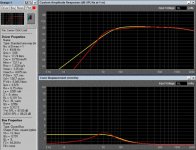
Some recommend increasing the capacitance of the output capacitor to expand the frequency range. This is not entirely true. In the case of using an acoustic design called a closed box, there is a way to improve the sound. It lies in the correct choice of the output capacitance for a particular type of speaker. In this case, the optimal capacitance value can be in the range of 500-1000 microfarads.
(The red graph corresponds to a capacitance of 500 microfarads).
https://sbacoustics.com/wp-content/uploads/2018/05/Capacitor-Tuning.pdf
(The red graph corresponds to a capacitance of 500 microfarads).
https://sbacoustics.com/wp-content/uploads/2018/05/Capacitor-Tuning.pdf
Attachments
Last edited:
I have a pair of Kef speakers that use this technique.
I wonder, though, how their sound has changed as the caps have aged and lost capacitance (I got them second hand, so don't know what they sounded like from new).
I wonder, though, how their sound has changed as the caps have aged and lost capacitance (I got them second hand, so don't know what they sounded like from new).
Lookin
Looking at the photos, it is beautifully constructed and probably much better than a DIYer can do. I have built a few using the 2SJ162 and the sound is as they quoted, warm, rich and relaxing. Use them with large, efficient speakers and you will rattle the windows, really. Bass is the nicest I have heard on any amplifier and reaches deep and non fatiguing. Good luck with it, it is really a classic sound from a classic amplifier. I actually prefer it with the Lateral MOSFETs than modern transistors, which in my opinion sounds more like the original 2N3055.I should have researched more of what's currently available in finished form, from China. There is, apparently, a lateral mosfet JLH version from Breeze HI-FI who may be just one of several sellers. I can't accept that its mosfets are branded TOSHIBA but also marked J162, which is a Renesas part number, though. As usual, there's something misleading about their promotional blurb but I wonder what's really inside and how the finished product sounds...?? A friend has one on order so I hope to hear for myself when it arrives. https://www.aliexpress.com/item/1005005050098088.html?
I can't believe it runs pure class A for 10 watts given the size of those heatsinks.
Ah well. So long as it doesn't sound greasy.
Ah well. So long as it doesn't sound greasy.
- Home
- Amplifiers
- Solid State
- JLH 10 Watt class A amplifier