Indeed, you do have a fine collection of parts👌- and taken precautions like buying in tape and reel form too. However, I wasn't questioning your build or parts stocks. My comment is directed mainly to newbies; by far the biggest active proportion of JLH69 and similar small kit assemblers/users.I'm sure that all the transistors I have are original. Most of them were bought 30 years ago. At that time, my country was not made in China 🙂
But still the ksc 3503 sound more musical, closer to the tube amp
The plate under the transformer is 1 cm thick. It is not possible to stretch. The transformer is connected to the plate at 2 points. The bottoms of the other legs are filled with felt. Air flow is provided from under the transformer. The temperature of the plate is not transmitted to the transformer either. The transformer is electrically isolated from the plate. The transformer is also connected to the main earth. Connection screws is also isolated
View attachment 1118820View attachment 1118821
Some years ago, as Chinese origin kits were becoming ever cheaper and the obsolete parts were commonly substituted or faked, some of the tricks were quite obvious. With 2N1711 as an example, you could easily rub the ink markings off with a finger. Later, the ink was replaced by a proper enamel type but whilst working OK, the transistor die was still questionable as being the same marked type. I have no solid proof, but on listening and a few basic tests, I concluded that what was inside was likely a common 2SD667/669 or similar clone chip. My experience with some of these small Japanese driver types, is that they are fine in the application anyway but if you expect genuine semis with factory and authorized distributor guarantees, you'll have to spend a lot more and await the pleasure of some traditional distributor.

So when you use metaphors to talk about sound, it puzzles me but everyone sees what they want to see, but this is really nonsense, it smacks of conspiracy and it doesn't. nothing to do here.;-)
Not credible for a commonly trained electrical engineer. But for physicians trained in this field or scientists in the field of mobile radio, military, secret service...).
Mobile radio is THE key technology of the New World Order. The electromagnetic fields serve not only the transmission of porn and cat pictures, but the control, monitoring, control and also sanctioning, up to killing. And low frequency emf are really easy to apply for mentioned "incidents"-)-;
;-)So when you use metaphors to talk about sound, it puzzles me but everyone sees what they want to see, but this is really nonsense, it smacks of conspiracy and it doesn't. nothing to do here.
For example, what is currently seen in the civilized world, the public:
Questions about questions:
https://video.icic-net.com/w/sdWHeFYZcMM4p4RvSncnDF
to the above, we can add that the vibration isolation of the power transformerQuote, OldDIY: Can I add vibration isolation pad (mat) under the transformer?
An isolation pad would have to support the mass of the transformer + any necessary mounting force. That's not simple to do because most synthetic foam materials are too soft, compressing down to nothing after some period of time at typical transformer operating temperatures. A piece of say, 8-12 mm solid but relatively soft neoprene rubber sheet laminated with rigid insulation board, could be effective though. Closed-cell neoprene foam sheeting is available too but I doubt its longevity. Here in Oz at least, there are some heavy machinery installers and automotive suspension specialists who use and sell suitable thick neoprene and other sheet rubbers, in roll form but I have no idea of your local sources or minimum purchase quantities. You need only a little of the stuff and that makes it hard to find a seller.
should not worsen the grounding contact of the metal parts of the armored or rod transformer.
Someone has to sweep out the cobwebs occasionally - 'seems like a good time for it, while there are some new and former thread dwellers posting. No doubt, we'll be back to the wire cutters and solder part soon enough....
Speaking of building, I found a pair of tiny, 5 x 5 cm PCBs for a hexfet version of JLH'69 - forgotten in my stack of things to do. The boards are marked for IRF250 power mosfets but surely that means IRFP250 as they have linear spacings for TO3P, TO247, 264 etc. style pinouts. A number of old IRFP types have been particularly cheap from China over recent years and that's great but surely there are others, perhaps better suited to 10-15W of class A audio. I don't fancy TIP41C which is marked for the driver/splitter either. Any better suggestions for that role too?
Last edited:
Некоторые люди с большим успехом использовали 2SK1058 в качестве выходного каскада...Мощные мосфеты IRF250
https://ldsound.club/index.php?threads/ab1-gibridnyj-usilitel-moschnosti.291/page-11
Last edited:
;-)
I would use TIP41 for all.
FET TO3-types, all the old ones, Hitachi, original others, do sound horrible: Nothing for listen, enjoy music.
I would use TIP41 for all.
FET TO3-types, all the old ones, Hitachi, original others, do sound horrible: Nothing for listen, enjoy music.
Некоторые люди с большим успехом использовали 2SK1058 в качестве выходного каскада...
https://ldsound.club/index.php?threads/ab1-gibridnyj-usilitel-moschnosti.291/page-11

Please post in English.
Some people have used 2SK1058 as an output cascade with great success...
Thanks for the suggestion of Lateral mosfets with schematic, Old DIY. However, there is some problem with viewing the schematic which, according to a message, may be fixed later.
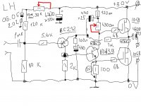
cumbb, the TIP41 is shown as the phase splitter/driver in this hexfet version. As such, it needs to be a fast, low capacitance type and that's s why a slug like TIP41 isn't a good choice. However, TIP41 is fine as the output and bias controller transistors in headphone versions. JLH specified a few alternative high frequency driver types with 2N1711 being the latest and still in production today. Others here seem to find 2SC3503 to be the best of all in that role.
If the old Hitachi Lateral mosfets sound consistently bad, it is most likely due to insufficient bias. The kit designers and some manufacturers were too cheap with bias which should be at least 100mA/device and running hot. Many products and kit designs were only getting 30-50mA. It was an opportunity for great sound in the 1980s but spoiled by unwise efforts to reduce power and parts costs.
Last edited:
problem with viewing the schematic
Attachments
ChaiFi kit recommends a quiescent current setting of 40-90mA. It's AB class 🙁kit designs were only getting 30-50mA
Member
Joined 2009
Paid Member
I have a chinese JLH69 and it uses p-type LatFETs, I guess there are plenty of p type left over after the single ended people scooped up all the n type. I don't know what is real or fake inside, or what bias it runs at but it does a good job of powering some Altec 808 compression drivers. What surprised me is that it still seems to have some of the characteristics of the sound of my DIY JLH69 which uses the venerable 2N3055 - maybe it's just that solid state class A have similar characteristics (smooth, slightly less treble bite than some of my AB amps).
When the Hitachi latfets appeared, I built a test amp, but the sound was not good to my ears. I have never used the parts since, and at the time I didn't have much in the way of test gear. What I recall is that what I tried to measure as an equivalent ft was around 2MHz, so not much of an improvement over the original RCA 2N3055. I'd agree it sounded a bit like a 3055 JLH, which is why I have considered using modern devices recently. I've heard better since using modern epi 2N3055/MJ2955, (in class AB) but not tested A:B as I no longer have a complete amp with the Hitachi's. I think caglarm's line-up should be pretty good (BC556B or similar input, KSC3503 driver and MJL3281 outputs).I have a chinese JLH69 and it uses p-type LatFETs, I guess there are plenty of p type left over after the single ended people scooped up all the n type. I don't know what is real or fake inside, or what bias it runs at but it does a good job of powering some Altec 808 compression drivers. What surprised me is that it still seems to have some of the characteristics of the sound of my DIY JLH69 which uses the venerable 2N3055 - maybe it's just that solid state class A have similar characteristics (smooth, slightly less treble bite than some of my AB amps).
I suspect modern lateral-vertical FETS with switching speeds in the 10MHz or higher will be far better.
And a TIP41 would not be suitable as a driver, as its fT is too low for good performance, as Ian mentions.
RenesasAre those Latfets obsolete Renesas, Hitachi or some copied product?
Thanks, Charm.
For anyone interested in the how and why of different types of power mosfets used in audio amplifiers, member Bob Cordell's book "Designing Audio Power Amplifers" is a must-read. It may not be cheap with all costs included but much cheaper and easier than attempting an MSc. degree in semiconductor physics.
The link below is to further comments and design work by another valued member here - PMA, at another forum. The thread there is trashed but PMA's OP is brilliant -a good introduction to the issues and discusses error correction in some detail, with good images. Perhaps though, that level of design work and comment is beyond the scope and interest of folk here who are considering only simple, low power applications like the OP, original JLH'69 design. https://www.audiosciencereview.com/...-power-amplifier-with-error-correction.37144/
If curious, there is a further link to Bob's website, book and commentary on power mosfets for audio here: http://www.cordellaudio.com/poweramp/why_mosfets.shtml.
Last edited:
use MOSFETs for JLH69 topology?I found a pair of tiny, 5 x 5 cm PCBs for a hexfet version of JLH'69 - forgotten in my stack of things to do. The boards are marked for IRF250 power mosfets but surely that means IRFP250 as they have linear spacings for TO3P, TO247, 264 etc. style pinouts. A number of old IRFP types have been particularly cheap from China over recent years and that's great but surely there are others, perhaps better suited to 10-15W of class A audio. I don't fancy TIP41C which is marked for the driver/splitter either. Any better suggestions for that role too?
it's a joke?
Just to explain my term "lateral-vertical" description of a MOSFET, I refer to the current flow pattern. This is laterally from the source, under the gate oxide, then vertically down towards the drain. OF course, most refer to these as vertical presumably because the drain is vertically underneath the source as opposed to lateral devices which have the drain in the same plane as the source.
- Home
- Amplifiers
- Solid State
- JLH 10 Watt class A amplifier