petr_2009,
Graham Maynard and everyone with his intellect can believe as much as they want the earth to be flat.
And of course, even an astronaut can't convince them otherwise.
Only people with negative intelligence can measure the frequency characteristics of the amplifier in such a perverse way and call it speed distortion.
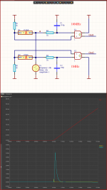
An amplifier with a bandwidth of 1MHz is 10 times better than one with a bandwidth of 10MHz.
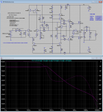
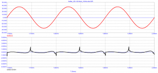
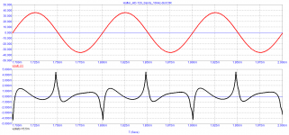
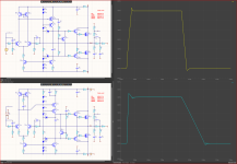
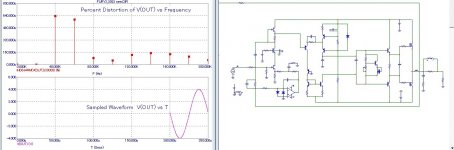
At the beginning of the sinuses there is an edge, and they are very harmonic with high frequencies.
1MHz amplifier will reduce these above 1MHz
10MHz amplifier will reduce them above 10MHz.
And when we subtract from the input signal the output we will see only the harmonics that the amplifier has not missed.
Therefore, we see a wider pulse and with a larger amplitude than a 1MHz amplifier, because there are harmonics with lower frequencies, compared to a 10MHz amplifier.
Out1 has a spectrum > 10MHz respectively on a plate and with a smaller amplitude
Out2 has a spectrum > 1MHz respectively longer and with a larger amplitude
So stop getting annoyed with the
In life, a sine with one frequency cannot immediately stop and start with another frequency, at this point there are already infinitely many harmonics.
And only an amplifier with a very high bandwidth >>>> 100MHz will reproduce them without cutting them.
However, in a musical signal that we give to an amplifier there are no signals with frequencies above 20KHz!!!!!!!!
And to cry that the amplifier wasn't fast enough is insane.
All modern amplifiers are enough and even too fast, and we even artificially reduce their frequency response by putting at the input RC circuit to cut the high frequencies >100kHz or >1MHz for example.
Graham Maynard and everyone with his intellect can believe as much as they want the earth to be flat.
And of course, even an astronaut can't convince them otherwise.
Only people with negative intelligence can measure the frequency characteristics of the amplifier in such a perverse way and call it speed distortion.
An amplifier with a bandwidth of 1MHz is 10 times better than one with a bandwidth of 10MHz.
At the beginning of the sinuses there is an edge, and they are very harmonic with high frequencies.
1MHz amplifier will reduce these above 1MHz
10MHz amplifier will reduce them above 10MHz.
And when we subtract from the input signal the output we will see only the harmonics that the amplifier has not missed.
Therefore, we see a wider pulse and with a larger amplitude than a 1MHz amplifier, because there are harmonics with lower frequencies, compared to a 10MHz amplifier.
Out1 has a spectrum > 10MHz respectively on a plate and with a smaller amplitude
Out2 has a spectrum > 1MHz respectively longer and with a larger amplitude
So stop getting annoyed with the
In life, a sine with one frequency cannot immediately stop and start with another frequency, at this point there are already infinitely many harmonics.
And only an amplifier with a very high bandwidth >>>> 100MHz will reproduce them without cutting them.
However, in a musical signal that we give to an amplifier there are no signals with frequencies above 20KHz!!!!!!!!
And to cry that the amplifier wasn't fast enough is insane.
All modern amplifiers are enough and even too fast, and we even artificially reduce their frequency response by putting at the input RC circuit to cut the high frequencies >100kHz or >1MHz for example.
Attachments
Last edited:

Sandy, do you even understand what nonsense you write?And when we subtract from the input signal the output we will see only the harmonics that the amplifier has not missed.
So you're denying that the best amplifier is the one that repeats the input audio signal 1:1. But for this, Kirill Hammer's statement that in order to transmit a signal as accurately as possible by an amplifier with a negative feedback, the signal propagation delay time should be only a few ns should be fulfilled.
And if you can’t fulfill this condition, don’t dream about sound quality! or make amplifiers without negative feedback, which is what many competent developers do.
It is a lot less rough in terms of loading the VAS. I would expect it to have better sound quality based on that alone. But if one wanted to keep the existing compensation, all we have to do is increase the current in the VAS to around 10 mA, and the problem largely goes away. Of course this would ideally require devices that can handle the dissipation and can be heatsinked, like KSC3503/KSA1381 for example. Increasing the current in the input stage wouldn't hurt either, along with increasing degeneration.my opinion is that your implementation of bipolar correction is very rough and in fact will not change anything in the subjective perception of the audio sound of the amplifier.
As far as what it would really sound like, only way to know that would be to build it. Sadly I don't have a DH-120 to experiment on. I used to have a DH-220 but that is a different design. It didn't sound bad, but didn't sound great either.
petr_2009,
It is clear to everyone that you are at odds with both electronics and common sense.
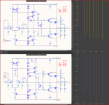
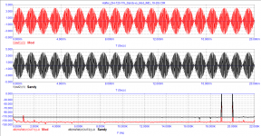
Audio amplifiers are designed to reproduce a maximum of 20KHz and the maximum of the signals you need to test them with are for example 100KHz
Let's say this is a reasonable stock, albeit a small high one.
You supposedly put an RC circuit to cut frequencies above 100KHz but because you have no idea even electrical engineering you do not understand that it does not cut it but only reduces their amplitude.
But you still have no idea even of arithmetic, do not parse that it will reduce harmonics with a slope of 20dB
1MHz will decrease 10 times, 10MHz 100 times.
But if we chase an accuracy of 0.1%, we need a reduction of more than 1000 times.
And if we are talking about 0.01% we already need 10,000 times.
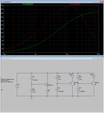
In other words, in order for this insane measurement to be correct, you need to reduce the harmonics of, and over 100KHz, to levels smaller than -80dB.
You can see from the example above that the same schizophrenic distortion is produced by a simple RC circuit and delay liny, without any feedbacks.
And this is the result of your endless ignorance of elementary physical things, and your inability to think logically.
It is clear to everyone that you are at odds with both electronics and common sense.
Audio amplifiers are designed to reproduce a maximum of 20KHz and the maximum of the signals you need to test them with are for example 100KHz
Let's say this is a reasonable stock, albeit a small high one.
You supposedly put an RC circuit to cut frequencies above 100KHz but because you have no idea even electrical engineering you do not understand that it does not cut it but only reduces their amplitude.
But you still have no idea even of arithmetic, do not parse that it will reduce harmonics with a slope of 20dB
1MHz will decrease 10 times, 10MHz 100 times.
But if we chase an accuracy of 0.1%, we need a reduction of more than 1000 times.
And if we are talking about 0.01% we already need 10,000 times.
In other words, in order for this insane measurement to be correct, you need to reduce the harmonics of, and over 100KHz, to levels smaller than -80dB.
You can see from the example above that the same schizophrenic distortion is produced by a simple RC circuit and delay liny, without any feedbacks.
And this is the result of your endless ignorance of elementary physical things, and your inability to think logically.
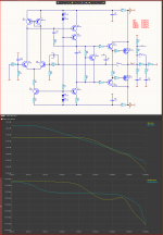
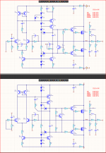
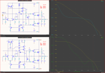
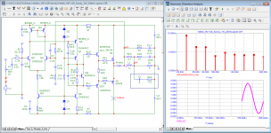
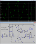
The traditional unipolar Müllerian frequency correction.
And 2 to 70 times lower THD.
And with fewer elements though only resistances and capacitors.
And 2 to 70 times lower THD.
And with fewer elements though only resistances and capacitors.
Attachments
Sure, but it required replacing the current mirror and VAS input transistors with faster ones in order to push GBW to 8 MHz. That could be tricky if layout is not optimal...which might be the case with the DH-120. The lack of emitter degeneration in the input stage could make it susceptible to RF interference.The traditional unipolar Müllerian frequency correction.
And 2 to 70 times lower THD.
And with fewer elements though only resistances and capacitors.
With TPC we can get better THD at only 3 MHz GBW and similar phase/gain margins. Assuming I replace the same transistors. Although it won't have as good slew rate.
In any case, it turns out that amp has a speaker fuse that is not enclosed in the feedback loop, and that may end up affecting it's subjective audio quality as well.
Attachments
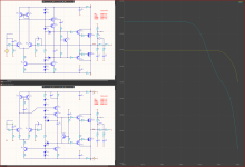
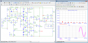
For me, THD is not so important to be as small as possible, it is also important how to achieve it.
I prefer unipolar corrections.
I changed the transistor because they don't have to be high-voltage and because the BC5xx have a larger h22e, are not higher frequency and do not increase GBW.
The gain increases only for the lowest frequencies, where the frequency correction no longer works. (DC)
With 2N5401 the difference will be minimal.
This does not affect GBW. And if you want a low GBW just increasing the capacity of the frequency correction.
Emitter resistors at the input in no way affect the RF disturbance there is an input RC circuit for them.
With 2N5401 I see a decrease in phase margin from 60 degrees to 48 degrees.
My Ft sims are showing the BC557C to have about 3 times the Ft at 500uA. (Simulation at 10 MHz). This explains the drop in phase margin. Might not be a big deal since lead inductance for the MOSFETs doesn't degrade phase margin much. More of an issue for BJT output stage, I think. I try to shoot for at least 70 degrees phase margin.
My Ft sims are showing the BC557C to have about 3 times the Ft at 500uA. (Simulation at 10 MHz). This explains the drop in phase margin. Might not be a big deal since lead inductance for the MOSFETs doesn't degrade phase margin much. More of an issue for BJT output stage, I think. I try to shoot for at least 70 degrees phase margin.
Attachments
The problem will not disappear anywhere, because. in your reasoning, you consider frequency correction only relative to VAS stage, however, the input stage(TS) also has gain, and the sound depends on its mode of operation. because it works on the capacitance of VAS cascade , including the dynamic one.It is a lot less rough in terms of loading the VAS. I would expect it to have better sound quality based on that alone. But if one wanted to keep the existing compensation, all we have to do is increase the current in the VAS to around 10 mA, and the problem largely goes away.
By suggesting to increase the current of the cascade Vas, you will only reduce its gain, yes, this will increase the linearity, but will reduce the depth of the overall negative feedback. Pay attention to the stages of the CFA amplifier in the subject, the input stage does not amplify anything in a wide frequency band, and has a relatively high current., The correction is determined by the value of the capacitance in the load of the stage and the value of the ohistor in the current feedback circuit. If we consider the classical VFA , for a large increase in the feedback depth, it is necessary that the input stage(IS) amplifies, but its gain is limited in frequency by at least a decade from the unity gain frequency. so that there is no need to increase the current in VAS stage.

In order for a comparison to be correct, you need to compare things not only by one parameter that is specifically high at the expense of all others.
Attachments
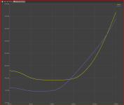
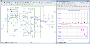
Well, it's true that most of the time music has small amplitudes and that's reasonable.
But an amplifier has to be pretty bad to distort a lot of 1W.
And the many audio designers purposely watch distortions at only a few power (W) because they find it difficult to make them distort a little at high power.
I prefer to compare different circuits at 90% of the level at which the amplifier enters the clip.
There are also the biggest THDs and if everything is satisfactory at 1W it can't be bad.
how much will fit?Many developers attach great importance to the distortion of the first watt 🙂
Attachments
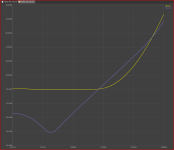
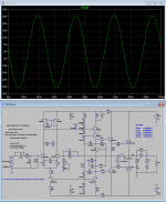
The use of JFET at the input of this parallel feedback loses all meaning.
And look at the other things on this scheme PSRR response to pulse signals.
A real scheme is a successful collection of many conflicting compromises.
And look at the other things on this scheme PSRR response to pulse signals.
A real scheme is a successful collection of many conflicting compromises.
You keep confusing sound quality with sick imagination, and you're not the only one who gets it.
In principle, nothing correlates with the diseased imagination, not even the invented schizophrenic distortions. 😉
In principle, nothing correlates with the diseased imagination, not even the invented schizophrenic distortions. 😉
the meaning was "open input" and only, and that high input impedance is not needed ...The use of JFET at the input of this parallel feedback loses all meaning.
subjectively compared the sound of Jfet at the input and a bipolar assembly with a floating input follower. Jfet was preferable.
The problem I was referring to is the inability of the VAS to drive the heavy loading at high frequencies, that is all. You are right about the reduction of VAS gain and hence loop gain, but this can be compensated by increasing the VAS load resistor value. Of course we no longer have a flat loop gain in the audioband and this is going to bother some people. We only need to increase VAS current to 5 mA. ULG is still reasonable at 4 MHz (a slight increase) with 46 degree phase margin, similar as original circuit.The problem will not disappear anywhere, because. in your reasoning, you consider frequency correction only relative to VAS stage, however, the input stage(TS) also has gain, and the sound depends on its mode of operation. because it works on the capacitance of VAS cascade , including the dynamic one.
By suggesting to increase the current of the cascade Vas, you will only reduce its gain, yes, this will increase the linearity, but will reduce the depth of the overall negative feedback. Pay attention to the stages of the CFA amplifier in the subject, the input stage does not amplify anything in a wide frequency band, and has a relatively high current., The correction is determined by the value of the capacitance in the load of the stage and the value of the ohistor in the current feedback circuit. If we consider the classical VFA , for a large increase in the feedback depth, it is necessary that the input stage(IS) amplifies, but its gain is limited in frequency by at least a decade from the unity gain frequency. so that there is no need to increase the current in VAS stage.
Attachments
In principle, nothing correlates with the diseased imagination, not even the invented schizophrenic distortions. 😉
Written with understanding, by any chance not from ward number 6?
- Home
- Amplifiers
- Solid State
- Apex A40 fundamental improvement. (Sandy)