Mental distortion is just the highest score😀. Many audiophiles suffer from this. And I recognize this style of commenting😉

Distortions are of only two kinds.
Change in gain from frequency, and change in gain from instantaneous amplitude.
All the rest are inventions of people without technical culture.
Distortion is constantly confused with the method of its measurement.
Technically untrained audiophiles mistake three different distortions for three methods of measuring the same thing.
And accordingly, if you do not understand what you are measuring, you will never understand what causes it and how to reduce it.
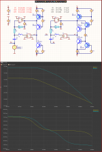
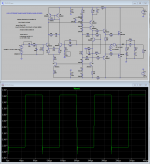
Here are the output resistances and output resistances of a common VAS (common base ) and TIS at different output voltages -45V, 0V +45V!
And the gain is the output resistance times the steepness of the input stage (S) chosen here 10mA/V is about as much as an input stage with a JFET.
We see the huge difference of 6.8 times, which makes for huge distortion (THD) without feedback.
Change in gain from frequency, and change in gain from instantaneous amplitude.
All the rest are inventions of people without technical culture.
Distortion is constantly confused with the method of its measurement.
Technically untrained audiophiles mistake three different distortions for three methods of measuring the same thing.
And accordingly, if you do not understand what you are measuring, you will never understand what causes it and how to reduce it.
Here are the output resistances and output resistances of a common VAS (common base ) and TIS at different output voltages -45V, 0V +45V!
And the gain is the output resistance times the steepness of the input stage (S) chosen here 10mA/V is about as much as an input stage with a JFET.
We see the huge difference of 6.8 times, which makes for huge distortion (THD) without feedback.
Attachments
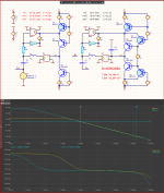
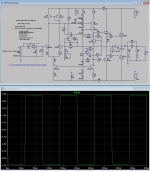
Introducing the frequency correction C3=3.5pF reduces distortion without feedback, because in addition to the output resistance and output capacitance, which change and introduce THD, we put something larger that does not change.
And so the total change becomes much smaller at R-17 times C-157 times
Accordingly, it reduces the THD without feedback this many times, and the feedback for 1KHz is 63.6dB 1500 times.
So the THD will be reduced another 1500 times.
And so the total change becomes much smaller at R-17 times C-157 times
Accordingly, it reduces the THD without feedback this many times, and the feedback for 1KHz is 63.6dB 1500 times.
So the THD will be reduced another 1500 times.
Attachments
Distortions are of only two kinds.
Change in gain from frequency, and change in gain from instantaneous amplitude.
Changes in both the amplitude of the signal and the frequency of the signal lead to the appearance of the same type of distortion, namely, distortions of the SID type associated with a deviation from a pure sinusoid (I conditionally called them high-speed distortions, I repeatedly gave examples of tests).
This kind of distortion depends primarily on the Group Delay and its behavior far beyond the audio range. Some audio amplifier designers rely only on THD measurements and are disappointed with the sound quality as a result (or admire the number of zeros after the decimal point obtained in the simulator on ideal component models), other developers like Charles Hansen, Nelson Pass, John Curl, Mike Malinowksi and many others more trust their ears, so the sound quality of their developments compares favorably.
As far as THD is concerned, dropping below 0.1% is meaningless if the distortion product spectrum is short, as in reference tube amps.
p.s. look, with time you will see clearly
What you see is the sum of the linear and non-linear distortions.
And it's the stupidest measurement you can think of, especially with a delay line.
And it's stupid because by looking at the sum of 2 things, you have no idea which of the two is how much.
Not to mention that using a delay line degrades the result.
Mental distortion!
And it's the stupidest measurement you can think of, especially with a delay line.
And it's stupid because by looking at the sum of 2 things, you have no idea which of the two is how much.
Not to mention that using a delay line degrades the result.
Mental distortion!
where does this number come from? who will confirm it?As far as THD is concerned, dropping below 0.1% is meaningless if the distortion product spectrum is short,
according to subjective estimates, the average listener ceases to detect distortions less than 0.04% (20 kHz) by ear, and this is subject to a short spectrum of these distortions.
where does this number come from? who will confirm it?
according to subjective estimates, the average listener ceases to detect distortions less than 0.04% (20 kHz) by ear, and this is subject to a short spectrum of these distortions.
The Hafler HD-120 has a loop gain of 60 dB at 20 kHz. distortion at a frequency of 20 kHz does not exceed 0.005%, and in terms of sound it is inferior to simple vintage Rotel amplifiers with much more modest parameters.
https://www.diyaudio.com/community/threads/sound-quality-vs-measurements.200865/post-2833864
A miner and a composer hardly have the same THD perception threshold.
But if both are normal people, there is a threshold beyond which they say they can't hear a difference.
The problem is with the abnormal ones where such a threshold is missing, they hear even 0.000000000001% distortions.
And in order not to admit that they are just meek schizophrenics, they invent various types of non-existent distortions to calm their conscience.
Does the illogical frequency correction with a large number of capacitors in the emitter circuits of transistors and only one pair of high-resistance MOS Fet as power transistors bother you?The Hafler HD-120 has a loop gain of 60 dB at 20 kHz.
distortion at a frequency of 20 kHz does not exceed 0.005%,
with a long tail of the harmonic spectrum and a speaker system with a large impedance unevenness, the audio listener is able to distinguish distortions up to 0.001%, subjectively this is also confirmed by tests.
Because Rotel uses a classic amplifier topology with elements of progressive frequency correction.and in terms of sound it is inferior to simple vintage Rotel amplifiers with much more modest parameters.
.
Last edited:
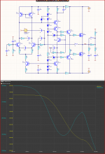
Here is the reason for bad sound!
The typical audiophile frequency correction with 2 poles to get some THD when measuring.
But such frequency correction is very harmful for accurate reproduction of pulse signals, and the sound signal does not look like a pure sine at all!
The typical audiophile frequency correction with 2 poles to get some THD when measuring.
But such frequency correction is very harmful for accurate reproduction of pulse signals, and the sound signal does not look like a pure sine at all!
Attachments
show deviations from pure sineHere is the reason for bad sound!
The typical audiophile frequency correction with 2 poles to get some THD when measuring.
But such frequency correction is very harmful for accurate reproduction of pulse signals, and the sound signal does not look like a pure sine at all!
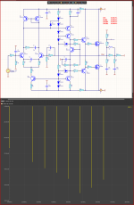
Seems to me the problem with the DH-120 is that it's VAS has inadequate standing current, resulting in slew induced distortion even at fairly low levels. It won't even output a 30 kHz sine wave at 35 V peak without gross distortion. That's not due to two pole compensation but how it's been implemented. A bit ironic given the choice to use fast MOSFETs. The problem can be alleviated even without increasing the VAS current. No, you won't get the same 20 kHz THD, but it will be considerably lower in the audio band due to additional loop gain. And CCIF 19+20 kHz IMD will actually be better in the "fixed" version. I did not spend that much time optimizing it, and further improvements are probably possible.
Attachments

And even the simulation matches well with the data provided by the company.
Sandy, distortion can be measured in different ways.
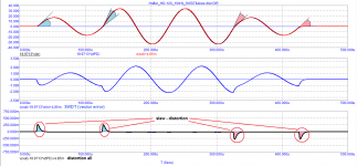
For example, Graham Maynard believed that the THD of a 10 kHz signal measured in the 1st period (FCD) correlates with the sound quality of an amplifier.
Here are two results of distortion measurements at 1 W output power: on the 4th period and at steady state. The transient distortions that Cortez paid attention to were also not canceled.
One can imagine what large distortions this amplifier will show in the first period, since they largely depend on tPD, especially for amplifiers with common feedback, since not only the delayed and phase-shifted output signal distorted by the reactive load is returned to the adder, but also the counter signal back emf.
Therefore, it is not surprising that, despite its negligible distortion in steady state at an active load (<0.001 ... 0.002%), it is inferior to vintage Rotel 800-series amplifiers with THD more than an order of magnitude higher during the development of which great attention was paid to listening, and not THD.
Attachments


my opinion is that your implementation of bipolar correction is very rough and in fact will not change anything in the subjective perception of the audio sound of the amplifier.That's not due to two pole compensation but how it's been implemented.
Therefore, it is not surprising that, despite its negligible distortion in steady state at an active load (<0.001 ... 0.002%), it is inferior to vintage Rotel 800-series amplifiers with THD more than an order of magnitude higher during the development of which great attention was paid to listening, and not THD.
I previously thought that with a Negative Feedback Depth of up to 30dB or more than 60dB at 20kHz, the amp automatically had good performance and sound. In fact, it turned out not to be so. Depending on the type of correction, the "dead zone" of the Feedback depth values for subjective sound quality is eliminated...
If it's fun for you, the group delay value has decreased by 8 times, but this was more of a bonus than the purpose of the modification.
this was said in reference to Marshall Leach's recent vintage amplifier modification project.If it's fun for you, the group delay value has decreased by 8 times, but this was more of a bonus than the purpose of the modification.
Distortions are of only two kinds.
Change in gain from frequency, and change in gain from instantaneous amplitude.
And accordingly, if you do not understand what you are measuring, you will never understand what causes it and how to reduce it.
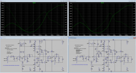
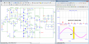
Sandy, if you understand what is what, then there are no problems with decoding the type of distortion. The distortion of the amplifier in steady state is negligible. The main distortions occur precisely at the moments of change in both the frequency of the signal and its amplitude.
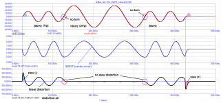
On the example with a frequency of 20 kHz, it is clearly seen that a signal with a frequency of 20 kHz has linear distortion due to the frequency response (a signal with a frequency of 20 kHz has a blockage in relation to a frequency of 10 kHz).
At the same time, there was no “slew” distortion even when both the frequency and amplitude of the signal were changed at the same time! 🙂
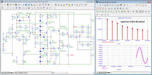
Initially, the distortion spectrum was measured on the 4th period (I note that we listen to music starting from the first period, whether it is a drum hit, a piano key or a cymbal).
The latest versions of the program do not allow you to measure distortion at earlier periods where distortion is maximum, as it was before the 9th version of the Micro Cap program inclusive.
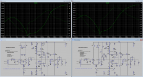
And here is the result of testing in steady state. As you can see in the steady state, both circuit options have the same parameters (this is what Aduoprecision will show).
Attachments
-
 06a_Hafler_HD-120_10kHz-SWDT.png16.6 KB · Views: 97
 -
 06b_Hafler_HD-120_20kHz&10kHz-SWDT.png20.5 KB · Views: 97
 -
 06c_Hafler_HD-120_10kHz_SWDT&slew-dist.png16.2 KB · Views: 107
 -
 08_Hafler_HD-120_1W_20kHz-spectr.png35.1 KB · Views: 117
 -
 08a_Hafler_HD-120_1W_20kHz-spectr.png35.4 KB · Views: 106
 -
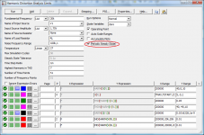 Harmonic Distortion Analysis Limits.png27.4 KB · Views: 98
Last edited:
- Home
- Amplifiers
- Solid State
- Apex A40 fundamental improvement. (Sandy)