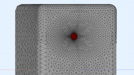
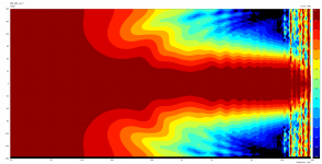
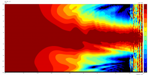
My efforts to control vertical pattern and at the same time create a wide disperson 60 degree horizontal pattern led to a very wiggly waveguide. Stupid, this only shows up with more resolution and calcultion time. Any tips how to improve the workflow for earlier detection and design appreciated.
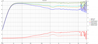
BTW, phase issue in exported FRD prevails, see VCad


BTW, phase issue in exported FRD prevails, see VCad
Yep it is not backwards compatible 🙂Oups, sorry, it works with the latest free version 3.1.7 b98...
I don't know what "git" would do but I have screwed up enough times trying to do something similar to just separate the directories now.Sorry for the tangent, but you could use "git" for source control? Then you could just stay in the same project directory, and create a new sim as a new git branch, then you can stay in one folder the whole time.
If you end up with a mesh that has too many thin triangles you get this sort of pattern, very much like a non unique problem, but turning NUC on does not help.My efforts to control vertical pattern and at the same time create a wide disperson 60 degree horizontal pattern led to a very wiggly waveguide. Stupid, this only shows up with more resolution and calcultion time. Any tips how to improve the workflow for earlier detection and design appreciated.
Try the zmap points to make the mesh have the triangles be all a very similar non thin shape or just ignore it as a simulation artefact.
With previous waveguides that did not treat vertical and horizontal pattern as different to the degree this one does, they did not show as many wiggles. And after all, Ath designs tried to combat this typical behaviour of commercial waveguides IIRC. Speaking of commercial designs: Does not the S360 waveguide response looks less struck by this behaviour? https://www.audiosciencereview.com/forum/index.php?threads/genelec-s360-review-studio-monitor.36187/, as well as Neumann's KH150? https://www.audiosciencereview.com/forum/index.php?threads/neumann-kh150.33454/post-1363792 If they can surpress the wiggles and do so, this should be possible for is to do too.
Just trying to learn what is achievable and desireable as a design goal.
Just trying to learn what is achievable and desireable as a design goal.
Re the availability if ABEC3: Is it legit to share the installer here, if they took it from the website? Many of us still have it on their HDD, I am sure.
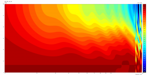
From the polar map alone it's not very clear what's going on but I would try to morph it into a (rounded) rectangle.
That did not work very well the last time, as the whole arrangement of parameters did not translate well to a rectangular device. Would you expect that a rectangular waveguide smoothens the field?
This is the RadImp plot for
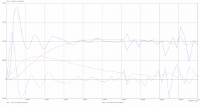
This is the RadImp plot for
Code:
Radiation_Impedance
  BodeType=Complex; GraphHeader="RadImp"
  Range_min=0; Range_max=2; RadImpType=Normalized
  403   1001 1001   ID=8001
  404   1002 1002   ID=8002
What do you mean, that the "whole arrangement of parameters did not translate well to a rectangular device"? There's the "Morph.*" feature that doesn't care what the original shape is, it just recalculates the whole shape so that it becomes exactly rectangular at the mouth (starting with the throat kept intact and progressively morphing the overall shape - as set with 'Morph.Rate').
Just set 'Morph.TargetShape = 1' and see what it does...
But perhaps you should first check with in infinite baffle that there's indeed some reflection within the waveguide itself.
Just set 'Morph.TargetShape = 1' and see what it does...
But perhaps you should first check with in infinite baffle that there's indeed some reflection within the waveguide itself.
I understood, however, last time that I had tried to transform an elliptical device to a rectangular, results where off quite far. I reasoned this was so because of a different surface ratio that the corners add. I will try the infinite baffle, good idea.
No not what I was talking about, the slight diffractive ripple that you term strong wiggles is hard to completely avoid when there is a complete baffle being modelled. The fully reflective boundaries highlight issues that you would not see in the same way in a real speaker.Interesting. Just to make sure we are on the same point: ... I mean the strong wiggles between 2 and 8 kHz.
It's not the resolution that creates the artefact but by increasing the mesh resolution there can be more chance of making meshes that are hard to solve, hence the garbage.I am not concerned about the splash >10k, which is a mere artifact of the resolution.
I can't see in enough to know but there is something wrong with it to get that sort of result.The mesh does not include thin triangles that should be problematic:
I can only say that when I used the same number of frequencies (300) for the range of 1k-20k, instead of 20-20k, the splashing from 15k was very little. I did not change the mesh settings.It's not the resolution that creates the artefact but by increasing the mesh resolution there can be more chance of making meshes that are hard to solve, hence the garbage.
As mabat suggested I have tried the waveguide on an infinite baffle. I had first assumed that the ripples in the horizontal pattern would stem from shaping the vertical axis to work "against" the horizontal. Sort of a two-profiles-in-one approach, but horizontal versus vertical instead of diagonals. It does not seem to be the reason:
The horizontal pattern simulated in a box, free standing, 300 frequencies gave this result:
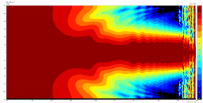
This is the same view, but on an infinite baffle, 300 frequencies:
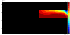
The horizontal pattern simulated in a box, free standing, 300 frequencies gave this result:

This is the same view, but on an infinite baffle, 300 frequencies:

Last edited:
The vertical axis was observed to be turbulent, what about the other angles?
Plots normalized to 10 deg, in 10 degree increments 0-90 deg (quarter profile), 300 frequencies. Click for carousel view to slide through:
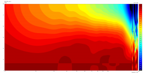
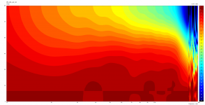
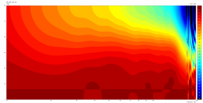
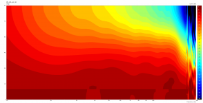
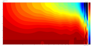
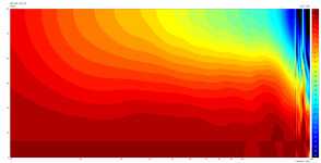
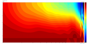
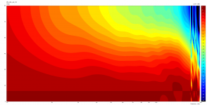
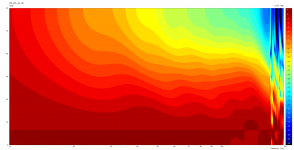
Non normalized, else same as above:
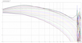
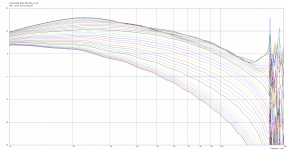
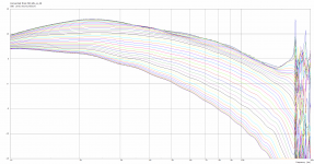
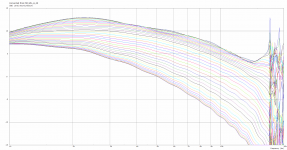
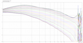
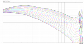
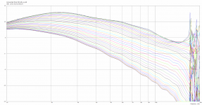
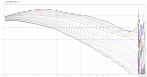
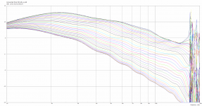
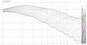
On the matter of the ripples in the horizontal pattern, I am still clueless. Does the vertical turbulences propagate differently through the wavefront if the waveguide is not mounted on an infinite baffle? Or the horizontal ripples do not come from the waveguide?
Plots normalized to 10 deg, in 10 degree increments 0-90 deg (quarter profile), 300 frequencies. Click for carousel view to slide through:


Non normalized, else same as above:


On the matter of the ripples in the horizontal pattern, I am still clueless. Does the vertical turbulences propagate differently through the wavefront if the waveguide is not mounted on an infinite baffle? Or the horizontal ripples do not come from the waveguide?
Last edited:
I still believe that the pristine performace of the latest free standing waveguides (as shown in this thread) stems also from their ability to effectively shadow the front hemisphere from the reflections/diffractions of the sound that passes the mouth and gets behind the device (or an enclosure). This is not easily detectable by the common semi-anechoic techniques in limited spaces, as the reflected/diffracted sound from the back can be delayed on the order of several milliseconds behind the direct sound (it may partly show in an impulse response but could be effectively lost in frequency domain by a too short time window). It could be interesting to get an impulse response from the simulated data, to see if there's anything that resembles such phenomena.
Last edited:
Equipment
TC9FD18 sealed.
Motu M4, MC2 T4-250, Umik-2.
Results
Very quick measurements. Will set up properly tomorrow.
~1m from cone. Horizontal - green on axis, increments of ~10deg, 1/6th smoothing.
View attachment 1070175 View attachment 1070173 View attachment 1070174
Code:
; -------------------------------------------------------
; Horn Geometry
; -------------------------------------------------------

Throat.Profile = 1
Throat.Diameter = 76         ; [mm]
Throat.Angle = 30          ; [deg]
Length = 50

GCurve.Type = 2                ; superformula
GCurve.SF = 0.5, 0.5, 4, 1, 1.5, 1.5
GCurve.Width = 130
GCurve.Dist = 0.50

Term.s = 0.1
Term.n = 4
Term.q = 0.996

; -------------------------------------------------------
; Morph Settings
; -------------------------------------------------------

Morph.TargetShape = 1 ; rectangle
Morph.CornerRadius = 6
Morph.FixedPart = 0.0
Morph.Rate = 3
Morph.TargetWidth = 180
Morph.TargetHeight = 240
Morph.AllowShrinkage = 1

; -------------------------------------------------------
; Mesh Setting
; -------------------------------------------------------

Mesh.AngularSegments = 94
Mesh.LengthSegments = 20
Mesh.ThroatResolution = 4.0 ; [mm]
Mesh.InterfaceResolution = 8.0 ; [mm]
Mesh.CornerSegments = 7
Mesh.InterfaceOffset = 5.0 ; [mm]
;Mesh.ZMapPoints = 0.5,0.5,0.5,0.9

; -------------------------------------------------------
; ABEC Project Setting
; -------------------------------------------------------

ABEC.SimType = 1 ; infinite baffle
ABEC.Abscissa = 2 ; 1=log | 2=linear
ABEC.f1 = 20 ; [Hz]
ABEC.f2 = 20000; [Hz]
ABEC.MeshFrequency = 1000
ABEC.NumFrequencies = 15

ABEC.Polars:SPL = {
  MapAngleRange = 0,90,19
  NormAngle = 10    ; [deg]
  Distance = 3      ; [m]
  Offset = 51       ; [mm]
}

ABEC.Polars:SPL_V = {
  MapAngleRange = 0,90,19
  NormAngle = 10    ; [deg]
  Distance = 3      ; [m]
  Offset = 51       ; [mm]
  Inclination = 90
}

; -------------------------------------------------------
; Output
; -------------------------------------------------------

Output.DestDir = "C:\ath4" ; current directory by default

Output.STL = 1
Output.ABECProject = 1

Report = {
  Title = "Limacon TC9 v1"
  Width = 1920
  Height = 1080
  NormAngle = 10
  GnuplotCode = 2x2n.gpl
}

GridExport: = {
  ExportSlices=1
  ExportProfiles=1
}
Had a few enquiries about that TC9 experiment. I think this is the cfg I used at the time. Maybe can be optimised by others?
Last edited:
Just out of curiosity - has anyone identified any inexpensive (i.e. sub-$125/driver) that mate well with the ST260? I'd like to use something that would allow a crossover in the 1.2Khz+/- region.
Despite the various prints, I have yet to build a speaker with any waveguide that has come from this thread.
Despite the outstanding performance of the free-standing horns, I plan on utilizing the ST260B (baffle mounted).
Current drivers on hand to pair with:
Despite the various prints, I have yet to build a speaker with any waveguide that has come from this thread.
Despite the outstanding performance of the free-standing horns, I plan on utilizing the ST260B (baffle mounted).
Current drivers on hand to pair with:
- Satori WO24P-4, and
- FaitalPro 12PR320
Hi,Here's the ST260BLD, if anyone wants to explore the idea.
Ath 4.9 beta for testing still available on my website: https://www.at-horns.eu/
Code:; ST260BLD ; public release under CC BY-NC-SA 4.0 ; Marcel Batík, 2022 R-OSSE = { R = 130 r0 = 12.7 a0 = 8 - 35*sin(p)^4 a = 39.5 k = 3 r = 0.25 b = 0.29 m = 0.82 q = 4.5 } Mesh.LengthSegments = 40 Mesh.AngularSegments = 64 Mesh.SubdomainSlices = Mesh.ThroatResolution = 4 Mesh.MouthResolution = 8 Mesh.InterfaceResolution = 5 Mesh.RearResolution = 15 Source.Shape = 1 ABEC.SimType = 2 ABEC.MeshFrequency = 1000 ABEC.NumFrequencies = 40 ABEC.Abscissa = 1 ABEC.f1 = 200 ABEC.f2 = 20000 ABEC.Polars:SPL_H = { MapAngleRange = 0,180,37 NormAngle = 0 Distance = 1.5 } ABEC.Polars:SPL_V = { MapAngleRange = 0,180,37 NormAngle = 0 Inclination = 90 Distance = 1.5 } ABEC.SphericalField:1 = { Radius = 0.5 } Output.ABECProject = 1 Output.STL = 1 Report = { Title = ST260BLD PolarData = SPL_H ;Width = 1200 ;Height = 900 }
I tried to solve the script but got garbage, or at least I can't understand the results.
I am using gmsh-4.6.0-Windows64 and Ath 4.9.0-pre-release-221114.
BTW I used the same WG parameters with ath-4.8.3b2.exe and the profile seems different, is that expected?
If you streetch your budget some you can get this https://en.toutlehautparleur.com/speaker-phl-audio-3411-8-ohm-10-inch.htmlJust out of curiosity - has anyone identified any inexpensive (i.e. sub-$125/driver) that mate well with the ST260? I'd like to use something that would allow a crossover in the 1.2Khz+/- region.
Despite the various prints, I have yet to build a speaker with any waveguide that has come from this thread.
Despite the outstanding performance of the free-standing horns, I plan on utilizing the ST260B (baffle mounted).
Current drivers on hand to pair with:
I'm leaning towards the WO24 (and am willing to sacrafince efficiency for a little bass extension + box size)
- Satori WO24P-4, and
- FaitalPro 12PR320
- Home
- Loudspeakers
- Multi-Way
- Acoustic Horn Design – The Easy Way (Ath4)
