AK4499EX vs. AK4499EQ in a listening test - what kind of audible differences are to note ?
This question rises up in my head after reading this:
https://www.audiosciencereview.com/forum/index.php?threads/akm-is-dead.38857/
This question rises up in my head after reading this:
https://www.audiosciencereview.com/forum/index.php?threads/akm-is-dead.38857/
According to John Westlake who visited the AKM factory before the fire and heard the AK4498 prototype, AK4499EX is intended to help solve the type of problems explained in the following books:
https://www.amazon.com/Substrate-Coupling-Circuits-Microwave-Hardcover/dp/1596932716
https://link.springer.com/book/10.1007/978-1-4020-8166-8
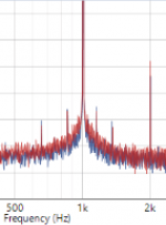
AK4499EX may not look much different on an FFT, but it may sound quite a bit different. Have to wait and see.
https://www.amazon.com/Substrate-Coupling-Circuits-Microwave-Hardcover/dp/1596932716
https://link.springer.com/book/10.1007/978-1-4020-8166-8
AK4499EX may not look much different on an FFT, but it may sound quite a bit different. Have to wait and see.

It is all about the implementation around the dac chip.
Here are 2 examples of AK4499EX dacs with quite different measurements:
https://www.l7audiolab.com/f/smsl-d400ex/
https://www.l7audiolab.com/f/vezzoso-x33/
Here are 2 examples of AK4499EX dacs with quite different measurements:
https://www.l7audiolab.com/f/smsl-d400ex/
https://www.l7audiolab.com/f/vezzoso-x33/
Somebody shall post complete datasheets please?
The AK form for download rejects gmail address, company only... 🙁
.
AK4499EXEQ Datasheet
English [220600017-E-00]
(54 Pages PDF: 2.08MB)
.
AKD4499EXEQ EVB Manual English [KM136300]
(53 Pages PDF: 2.71MB)
.
AK4499EXEQ Application Note
English [C018-01]
(24 Pages PDF: 1.04MB)
.
thanks
The AK form for download rejects gmail address, company only... 🙁
.
AK4499EXEQ Datasheet
English [220600017-E-00]
(54 Pages PDF: 2.08MB)
.
AKD4499EXEQ EVB Manual English [KM136300]
(53 Pages PDF: 2.71MB)
.
AK4499EXEQ Application Note
English [C018-01]
(24 Pages PDF: 1.04MB)
.
thanks
This is what I have on it: https://www.dropbox.com/sh/yfysp7l39d8k4z6/AABVmerS2FmfUAlF79swQdika?dl=0
pretty high Iout?
Can someone explain the diff between standard 1 data line DSD format and this "7-bits modulator data".
A very quick look at the specs showing that chip could be used without externally controlled registers?
but not 100% working...
Thanks.
Can someone explain the diff between standard 1 data line DSD format and this "7-bits modulator data".
A very quick look at the specs showing that chip could be used without externally controlled registers?
but not 100% working...
Thanks.
Maybe @MarcelvdG would be the best person to address that question. For myself, I would say that a 7-bit modulator could produce up to a 7-bit output, say, for PCM, but it could also produce a 1-bit output if desired. What it means in the latter context is that noise shaping can be more sophisticated/idealized as versus what is possible with a lower order modulator.Can someone explain the diff between standard 1 data line DSD format and this "7-bits modulator data".
Regarding using AKM chips operating without I2C register control, AKM often allows for something they call pin-mode control. Its appears to be sort of a dumbed down control scheme for low-cost applications. Don't know why they would bother with that for a top-of-the-line chip though.
Maybe @MarcelvdG would be the best person to address that question. For myself, I would say that a 7-bit modulator could produce up to a 7-bit output, say, for PCM, but it could also produce a 1-bit output if desired. What it means in the latter context is that noise shaping can be more sophisticated/idealized as versus what is possible with a lower order modulator.
Just a point about terminology - the number of bits in the modulator isn't its 'order'. The order tends to be related to the number of integrators in the loop, but Marcel would be the go-to guy on this. Higher order makes for a steeper noise-shaping filter and thus higher orders achieve higher SNRs for a given oversampling ratio.
Last edited:
Sorry. I agree about the terminology. IIUC with a 7th order modulator we could get 7-bits of PCM, is what I was thinking of. Each integrator offering one bit of additional resolution. But the modulator order doesn't need to be used that way. For DSD the output would still have to be only one bit.
abraxalito is correct, the order and the number of bits of the modulator data have nothing to do with each other. The only relation is that the higher the order and the higher the number of bits of the modulator data, the less quantization noise you have in the audio band.
A digital sigma-delta modulator or digital noise shaper is basically an oversampled feedback loop around a coarse quantizer. When you playback PCM, the quantizer rounds the digital data to some smaller word length - this word length is the number of bits of the modulator data. This rounding causes what is known as quantization noise, although whether it sounds as noise or as distortion on low-level signals depends on the circumstances. The feedback loop suppresses the quantization noise a lot in the audio band and makes it somewhat worse outside the audio band, at ultrasonic frequencies.
The feedback loop consists of a subtractor, a loop filter and the quantizer. The order refers to the order of the loop filter. It's normally a cascade of integrators (or accumulators if you want to be precise) with feedforward and feedback branches. The number of integrators is then the order. The higher the order, the better you can suppress the quantization noise in the audio band.
The signal from the modulator has to be converted to analogue by a DAC. Using only one bit of modulator data has the advantage that you need only a one bit DAC, which has only one step. You then don't have to worry about matching of the various steps of the DAC, as there is only one step (I'm neglecting some subtleties here). A disadvantage is that a one-bit quantizer causes a lot of quantization noise that you then have to get rid off, and that you can't properly dither a one bit quantizer. Dithering is a technique to ensure that quantization noise indeed sounds like noise.
When you use more than one bit of modulator data, you have to ensure that the various steps of the DAC match, otherwise that causes distortion again. There are techniques to control a bunch of unit DAC cells in such a way that the inaccuracies caused by mismatch between the DAC cells again ends up somewhere in the ultrasonic region.
Yes, but can we have more bits of modulator data than the number integrators (the order of the modulator)? If not, then there is some kind of relation between the two isn't there? IOW, can a modulator with one integrator directly produce enough bits of data to drive a dac with 10-steps? Or maybe digital downsampling could derive more steps from such a one-integrator modulator?...The only relation is that the higher the order and the higher the number of bits of the modulator data, the less quantization noise you have in the audio band.
EDIT: Thinking about it some more, if we have an integrator implemented with, say, 32-bit integer math, we could then map that to 10-steps pretty directly.
Last edited:
The first generation of Philips CD-players used a first-order noise shaper with 14 bit quantization, so the answer is definitely yes.
Drawing of a sigma-delta modulator (which is essentially the same as a noise shaper, the only difference being one feedforward branch in the filter), typical loop gain of a fifth-order modulator, resulting noise shaping curve.

The example loop gain is for a fifth-order modulator. Assuming unity quantizer gain, the loop gain is simply set by the gain of the loop filter.
When you arrange four of the filter's five integrators into two resonators, the loop gain goes to infinity at 0 Hz and at the resonant frequencies of the two resonators. At those frequencies, quantization noise is suppressed completely, in between not completely. At far ultrasonic frequencies, it actually gets a bit worse.
It works with any number >= 2 of quantizing levels, so any quantizer word length >= 1 bit, although there are some complications in the single bit case.
This is what I have on it: https://www.dropbox.com/sh/yfysp7l39d8k4z6/AABVmerS2FmfUAlF79swQdika?dl=0
Some fun on DAC board layer 4 at page 50, a black box covert over the central groundings....
someone protected or what's the beef about ... or one have the evaluation board in his hands 😳
As the black box hides some GND traces...
Hp
Attachments

It is interested that they use split ground. It gives more problems than advantages.Some fun on DAC board layer 4 at page 50, a black box covert over the central groundings....
someone protected or what's the beef about ... or one have the evaluation board in his hands 😳
As the black box hides some GND traces...
Hp
Robert Feranec has episode on his YT channel about this. More important is good placement of the elements and tracing and looks how the current flows. AKM deviding chips into to separatly modulator and analog part make more easier work for PCB designer.
It is interested that they use split ground. It gives more problems than advantages.
Robert Feranec has episode on his YT channel about this. More important is good placement of the elements and tracing and looks how the current flows. AKM deviding chips into to separatly modulator and analog part make more easier work for PCB designer.
In addition the jitter on 44.1kHz looks like as an functional evaluation kit, rather than a reference.
It may nice for the layouter to have more separated IC's, but at the end of the day the digital transmit RF to the DAC and this will end on the analog outputs. Digital and Analog chip is not galvanic isolated. Always interesting to use via(s) to connect GND layers for any blocking caps, as better closed to chip.
hp
Attachments
Not much sense using AKM evaluation boards as layout reference as they all are fundamentally flawed layouts with separate dac board on a "motherboard". Critical regulators too far off and no continuous ground planes. Most AKM evaluation boards do not actually reach datasheet performance levels.
- Home
- Source & Line
- Digital Line Level
- DAC AK4499EX Project