It was just stupidity. I mounted the boards at a 90 degree angle to the heatsink, with the output transistors connected though the underside of the board. Therefore all of them where flipped around so that emitter and base connections where flipped. This meant that the pnp side of the vas and output section couldn't work.What did you find, might help another forum member.
It's kind of an embarrassing mistake but also somewhat funny. I just wasn't thinking when planning the layout.
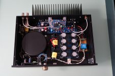
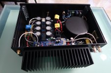
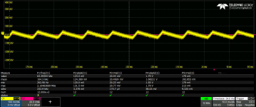
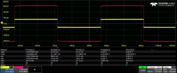
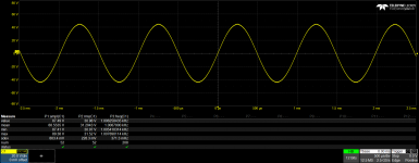
For those who are interested, I finished assembling my two mono amps. This time I made a stress test with a NON inductive load.
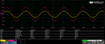
They can reach the continous power of 135 W / 8 ohms and 220W / 4 ohms each. That is more and more than enough for me!
Over this power I can see voltage drops as shown in the attached picture.
I also measured the ripple at the output of the power supply.
My trasfo are 400 VA 42 V and I use 8 x 10000 uF filter caps.
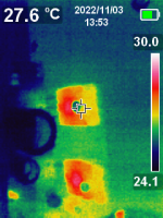
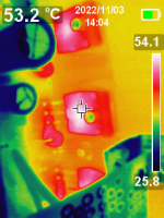
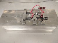
Transistors temperature is good, I used a huge heatsink!
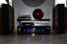
I connected them in my chain and the first impression is very good. Low frequencies are impressive.
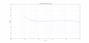
Next days I want to make some more measurements in the lab, like bandwidth, gain and THD.
Thanks to everybody for this good project!
They can reach the continous power of 135 W / 8 ohms and 220W / 4 ohms each. That is more and more than enough for me!
Over this power I can see voltage drops as shown in the attached picture.
I also measured the ripple at the output of the power supply.
My trasfo are 400 VA 42 V and I use 8 x 10000 uF filter caps.
Transistors temperature is good, I used a huge heatsink!
I connected them in my chain and the first impression is very good. Low frequencies are impressive.
Next days I want to make some more measurements in the lab, like bandwidth, gain and THD.
Thanks to everybody for this good project!
Attachments
-
 1W_4ohm.png33.9 KB · Views: 169
 -
 200w.png27.7 KB · Views: 178
 -
 200W_4ohm.png32.3 KB · Views: 176
 -
 220w.png26 KB · Views: 229
 -
 IMG_0816.JPG182.9 KB · Views: 249
 -
 IMG_0822.JPG199.4 KB · Views: 237
 -
 IMG_0830.JPG156.2 KB · Views: 205
 -
 load.jpg154.4 KB · Views: 189
 -
 ripple_0W.png30.7 KB · Views: 181
 -
 ripple_240W.png54 KB · Views: 166

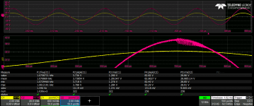
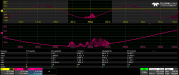
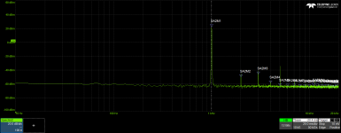
What's causing the HF in the 4th picture?For those who are interested, I finished assembling my two mono amps. This time I made a stress test with a NON inductive load.
They can reach the continous power of 135 W / 8 ohms and 220W / 4 ohms each. That is more and more than enough for me!
Over this power I can see voltage drops as shown in the attached picture.
I also measured the ripple at the output of the power supply.
My trasfo are 400 VA 42 V and I use 8 x 10000 uF filter caps.
Transistors temperature is good, I used a huge heatsink!
I connected them in my chain and the first impression is very good. Low frequencies are impressive.
Next days I want to make some more measurements in the lab, like bandwidth, gain and THD.
Thanks to everybody for this good project!
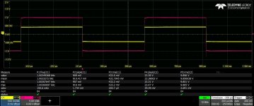
Good question. It happens just before to see the clipped sinusoid over 220W. So, I guess it's due to the transformer power limitation. To be sure I would have to replace it with a bigger one or use an external power supply without this limits, but I don't have any of them...
Last edited:
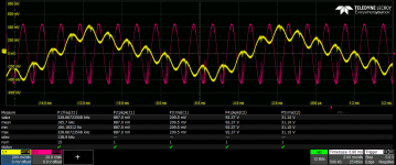
I think something else is going on... squinting it looks like 350 - 400 kHz oscillation. Maybe when you clip on the negative peak, the feedback loop is broken and that's what recovery looks like. What does the HF square wave response look like?More details... in yellow it is the voltage power supply. You can see some drop in coincidence with the output voltage.
The good news is #1 it looks like it only happens at clipping and #2 you could never hear it. I doubt it would make it down the average cable length.
That is the square response. In which conditions the feedback loop can break? Anybody else here has seen with a scope the waveform of this amp at full power? I used the BOM by mbrennwa with the only difference that I reduced the voltage gain a bit. I used R5=976 and R6=22k
Attachments
I don't see anything obvious in the square wave.
When you clip, you're not in the linear region so feedback is not working.
Lower gain = more feedback, you might need more feedforward cap on the upper feedback resistor.
Of course this all could just as well be much ado about nothing.
When you clip, you're not in the linear region so feedback is not working.
Lower gain = more feedback, you might need more feedforward cap on the upper feedback resistor.
Of course this all could just as well be much ado about nothing.
Do you mean to increase C3 and/or C4 to make a test?
In simulation I don't see any oscillation, so it's not easy to understand what to change
In simulation I don't see any oscillation, so it's not easy to understand what to change
I don't know your schematic so at this point I should let those with more knowledge weigh in. Like I said before it might not even be a problem.Do you mean to increase C3 and/or C4 to make a test?
In simulation I don't see any oscillation, so it's not easy to understand what to change
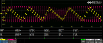
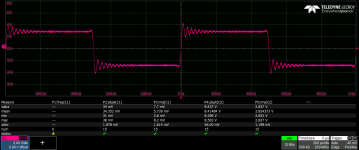
This looks like 50 kHz so probably not the same mechanism.I also have this one, taken with a faster generator. You can see some rings also at 1 W rms. Is this and indicator of HF instability? If yes, what can be changed?
Glad to heard that! About bass capacity, can you make a short comparison with other amplifier you tested before?I connected them in my chain and the first impression is very good. Low frequencies are impressive.
Thank you
Last edited:
I'm using the same Audio Analogue Puccini SE, now as preamp only. Speakers are still the same and the difference on the bass response is enormous. Rock and electronic music are born again! At the same time high frequencies are still good. Just for reference I will try to measure the differences between the two systems using Spectroid, also if the mic of the smartphone will have some limitation...Glad to heard that! About bass capacity, can you make a short comparison with other amplifier you tested before?
Thank you

The more I listen to it the more I like it and also it works better 🙃
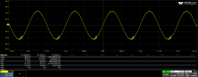
After few days of listening sessions I repeated the power measurements. Today it worked fine up to 140 W at 8 ohm without any oscillation! After that there is the clipping as expected. At 4 ohm I still see small oscillations but after 240 W, right before the clipping. Why did it changed? I really don't know, but I'm happy for it 🙂
After few days of listening sessions I repeated the power measurements. Today it worked fine up to 140 W at 8 ohm without any oscillation! After that there is the clipping as expected. At 4 ohm I still see small oscillations but after 240 W, right before the clipping. Why did it changed? I really don't know, but I'm happy for it 🙂
Attachments
I got it working finally. The annoying thing is that I actually don't know what the problem was exactly. I ended up replacing every transistor on the board and then it worked like a charm. But now I have another problem I can't figure out. Both channels have been running fine for several days without any problems. It seems like there is a distorted sound when playing music with lots of bass and "high vocals". It's not there in all types of music but sometimes in specific songs. Volume level does not seem to make any effect on the issue. I have taken both channels out on the bench and hooked them up and the problem seems to come from both boards. I don't have a good oscilloscope so it's a little difficult to track down where this problem is coming from.I would start by checkin wheter there is any connection between the heatsink and any of the transistors collectors. Maybe one of them is not properly insulated.
I hope that somebody can give me some pointers at where to look. It's so strange that the problem is coming from both channels even outside of the cabinet.
- Home
- Amplifiers
- Solid State
- diyAB Amp The "Honey Badger" build thread