Please change the zener diode to the one I recommend. R19 is 1watt. I mounted it under the pcbThanks for all the feed back everyone. I went back and checked everything and found that Q13 was measuring 55Mohms to the chassis. It turns out Kapton tape did not work as a great insulator. I also found that the fuse in the negative rail measured 1k ohms even though it was not blown and did not show any discoloration. After properly insulating Q13 from the chassis and replacing the fuse the amp fires up again and was able to set the bias, DC offset and R14 voltage.
I still have the speaker hum at idle and my next step is to Pull C6 and test, before change R19.
I have a question regarding grounding, since there seems to be so many differing opinions. Should I connect the signal ground to the chassis ground (120Vac plug ground), or should the audio reference voltage never connect to the mains ground?
Thanks again for all your help everyone.
There are photos in the thread.
Thanks Stuart. I ordered the recommended BZX55B15-TAP and the 15Kohm 1W resistor. Hopefully they will be here this week. In your schematic, are you replacing R19 with a 15kohm or are you putting it in parallel? Same question for R18 and C6.The Honey Badger has is own built in hum breaking resistor R4 4.7R.
Both RCA grounds tabs should be bonded together and connected to the chassis through a 1nf cap. See page 52 (81-RDER73A102K2M1H3A)
The connection of your main earth safety ground is connected to you amplifier PSU zero volt rail via a ground lift circuit.
There should be no connection from the PSU ground to the signal ground terminal. This is taken care of internally on the PCB through the R4.
All there details are in the document above.
Currently the whole amplifier is broken out on the bench and nothing is stuffed into the box. For my input source, I have a signal generator going straight into the input terminal block.Are your input jacks insulated from the chassis? Usually signal ground is connected to chassis ground through a ground breaker. Take a look at the attached document, it contains a lot of information that should fix your hum issues.
While waiting for new parts, I used a bridge rectifier to create the ground lifter indicated in the "how to wire an amplifier" document that was posted. There was no change in noise, so I added the resistor and capacitor suggested on Elliot Sound Products website. Still no change. With my scope hooked up to the output, and the signal generator disconnected, the scope shows a nice flat 0V signal. I have the signal generator turned off, and the amplifier powered off (power supply), but as soon as I connect the turned off signal generator, my scope shows 400 mVpp noise on the output. Disconnecting the signal generator wires at the input causes the noise goes away. It seems like my signal generator is somehow injecting noise, even while being turned off?
I guess the next path is to connect an MP3 player or a different device to the input.
Thanks again for all your help everyone.
They are not in parallel.Thanks Stuart. I ordered the recommended BZX55B15-TAP and the 15Kohm 1W resistor. Hopefully they will be here this week. In your schematic, are you replacing R19 with a 15kohm or are you putting it in parallel? Same question for R18 and C6.
.
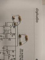
Those are the different options as noted in the build guide for the cascode voltage reference

Hi Sir I hope you doing great. I just wanted to know if I can get the files for the DAC, I would love to build that for my wolverine.DAC8 and Honeybadger
Hello all,
Little bit off-topic but I want to share my build of my DAC / Mediaplayer to go with my last years build of the Honeybadger Amp. (also very curious about the developments of Wolverine...).
Building both frames was quite a job, but it looks very nice together, and very happy with the sound of the badger combined with a quad PCM1704's.
T7 Honey Badger Amp


DAC8 DAC / Mediaplayer


Just wanted to chime in to give my feedback to anyone considering building the HB:
In short, DO IT. If you build it right, you have to spend multiples of your build cost to get anything that even EQUALS the performance, let alone exceeds it.
I put mine together with the parts listed below. Feel free to pilfer my recipe. All electrolytic caps are audio grade Nichicon and Elna, good aluminum polys for the smaller values. Vishay MKT for signal path film caps. All resistors are hand selected metal film, Dale where possible. Power supply is an Antek 1000VA 40-0-40 toroid with 80,000uf of Kemet audio grade filter caps. 56V rail voltages. I run modified Magnepan LRSs and there is plenty of drive and headroom on tap for those.
I repair audio gear for a living and that gives me the opportunity to test a lot of cool stuff in my system, and I can safely say that you need to spend a lot of money to beat my HB. In fact the only amp I can say performed better was a Pass Labs X250.5, and it was only slightly better in terms of bass control and imaging. The Threshold T200 was a near dead-ringer for the sonic signature of the HB
.
For about 1200$CAD invested in my build, I'm more than satisfied! I'd have to spend at 10x that to get something better.
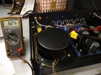
I run my bias hot, 50mv. Best results were anything above 30mv, diminishing returns as you go up. I subscribe to Nelson Pass' philosophy of running as much bias you can safely with the heat dissipation on offer. CCS current 8.25V.
For optimum accuracy run a Vishay MKT on the input cap. For slightly smoother top end but better soundstaging I run a 1uf Jantzen Silver Z.
Q1 NPN Input Transistor (LTP) ZTX1051A
Q2 NPN Input Transistor (LTP) ZTX1051A
Q3 NPN Transistor (Cascode/Current Mirror) KSC1845F
Q4 NPN Transistor (Cascode/Current Mirror) KSC1845F
Q5 PNP Transistor (Cascode/Current Mirror) KSA992F
Q6 PNP Transistor (Cascode/Current Mirror) KSA992F
Q7 NPN Transistor (LTP CCS) KSC1845F
Q8 NPN Transistor (LTP CCS) KSC1845F
Q9 PNP Transistor (VAS/CCS) KSA992F
Q10 PNP Transistor (VAS/CCS) 2SA1220A
Q11 NPN Transistor (VAS/CCS) 2SC2690A
Q12 NPN Transistor (VAS/CCS) 2SC2690A
Q13 NPN Transistor (VBE Multiplier) 2SC2690A
Q14 NPN Driver Transistor MJE15030G
Q15 PNP Driver Transistor MJE15031G
Q16 NPN Output Transistor 2SC5200OTU
Q17 NPN Output Transistor 2SC5200OTU
Q18 NPN Output Transistor 2SC5200OTU
Q19 PNP Output Transistor 2SA1943OTU
Q20 PNP Output Transistor 2SA1943OTU
Q21 PNP Output Transistor 2SA1943OTU
D1 Fast Switching Diode 1N4148
D2 Fast Switching Diode 1N4148
D3 15V Zener Diode 1N4744A
D4 Ultrafast Rectifier 1N5408
D5 Ultrafast Rectifier 1N5408
D6 Light Emitting Diode 3mm Red
D7 Light Emitting Diode 3mm Green
D8 Ultrafast Rectifier 1N5408
D9 Ultrafast Rectifier 1N5408
D-BC Baker Clamp Diode BAV21
R1 Resistor 100K 1/4W
R2 Resistor 820R 1/4W
R3 Resistor 33K 1/4W
R4 Resistor 4.7R 1/4W
R5 Resistor 820R 1/4W
R6 Resistor 33K 1/4W
R7 Multiturn Trimmer Resistor 200R
R8 Resistor 100R 1/4W
R9 Resistor 100R 1/4W
R10 Resistor 22R 1/4W
R11 Resistor 10K 1/4W
R12 Resistor 10K 1/4W
R13 Resistor 15K 1/4W
R14 Resistor 2.2K 1/4W
R15 Resistor 100R 1/4W
R16 Resistor 100R 1/4W
R17 Multiturn Trimmer Resistor 1K
R18 Resistor 22K 1/4W
R19 Resistor 15K 1W
R20 Resistor 220R 1/4W
R21 Resistor 220R 1/4W
R22 Resistor 820R 1/4W
R23 Resistor 33R 1/2W
R24 Resistor 820R 1/4W
R25 Resistor 220R 1/4W
R26 Resistor 100R 1/4W
R27 Resistor 68R 1/2W
R28 Resistor 2.2K 1/4W
R29 Resistor 680R 1/4W
R30 Multiturn Trimmer Resistor 500R
R31 Resistor 15R 1/4W
R32 Resistor 22R 1/2W
R33 Resistor 22R 1/2W
R34 Resistor 22R 1/4W
R35 Resistor 22R 1/4W
R36 Resistor 150R 1W
R37 Resistor 2.2R 1W
R38 Resistor 2.2R 1W
R39 Resistor 2.2R 1W
R40 Resistor 2.2R 1W
R41 Resistor 2.2R 1W
R42 Resistor 2.2R 1W
R43 Power Resistor 0.22R 5W
R44 Power Resistor 0.22R 5W
R45 Power Resistor 0.22R 5W
R46 Power Resistor 0.22R 5W
R47 Power Resistor 0.22R 5W
R48 Power Resistor 0.22R 5W
R49 Power Resistor 10R 3W
R50 Power Resistor 10R 3W
R51 Resistor 22K 1/4W
R52 Resistor 100K 1/4W
R53 Not used
R54 Not used
C1 Polypropylene Capacitor 4.7uf 100V
C2 Film Capacitor 270pf 100V
C3 Film Capacitor 0.1uf 100V
C4 Non-Polar Electrolytic Capacitor 220uf 50V
C5 Electrolytic Capacitor 47uf 100V
C6 Film Capacitor 0.22uf 100V
C7 Silver Mica 100pf 500V
C8 Silver Mica 470pf 500V
C9 Electrolytic Capacitor 22uf 100V
C10 Film Capacitor 0.1uf 100V
C11 Electrolytic Capacitor 470uf 63V
C12 Film Capacitor 0.1uf 100V
C13 Electrolytic Capacitor 2200uf 63V
C14 Film Capacitor 0.1uf 100V
C15 Electrolytic Capacitor 470uf 63V
C16 Film Capacitor 0.1uf 100V
C17 Electrolytic Capacitor 2200uf 63V
C18 Film Capacitor 47pf 100V
C19 Film Capacitor 47pf 100V
C20 Film Capacitor 2.2uf 100V
C21 Film Capacitor 0.1uf 250V
LC Cap Not used
In short, DO IT. If you build it right, you have to spend multiples of your build cost to get anything that even EQUALS the performance, let alone exceeds it.
I put mine together with the parts listed below. Feel free to pilfer my recipe. All electrolytic caps are audio grade Nichicon and Elna, good aluminum polys for the smaller values. Vishay MKT for signal path film caps. All resistors are hand selected metal film, Dale where possible. Power supply is an Antek 1000VA 40-0-40 toroid with 80,000uf of Kemet audio grade filter caps. 56V rail voltages. I run modified Magnepan LRSs and there is plenty of drive and headroom on tap for those.
I repair audio gear for a living and that gives me the opportunity to test a lot of cool stuff in my system, and I can safely say that you need to spend a lot of money to beat my HB. In fact the only amp I can say performed better was a Pass Labs X250.5, and it was only slightly better in terms of bass control and imaging. The Threshold T200 was a near dead-ringer for the sonic signature of the HB
.
For about 1200$CAD invested in my build, I'm more than satisfied! I'd have to spend at 10x that to get something better.
I run my bias hot, 50mv. Best results were anything above 30mv, diminishing returns as you go up. I subscribe to Nelson Pass' philosophy of running as much bias you can safely with the heat dissipation on offer. CCS current 8.25V.
For optimum accuracy run a Vishay MKT on the input cap. For slightly smoother top end but better soundstaging I run a 1uf Jantzen Silver Z.
Q1 NPN Input Transistor (LTP) ZTX1051A
Q2 NPN Input Transistor (LTP) ZTX1051A
Q3 NPN Transistor (Cascode/Current Mirror) KSC1845F
Q4 NPN Transistor (Cascode/Current Mirror) KSC1845F
Q5 PNP Transistor (Cascode/Current Mirror) KSA992F
Q6 PNP Transistor (Cascode/Current Mirror) KSA992F
Q7 NPN Transistor (LTP CCS) KSC1845F
Q8 NPN Transistor (LTP CCS) KSC1845F
Q9 PNP Transistor (VAS/CCS) KSA992F
Q10 PNP Transistor (VAS/CCS) 2SA1220A
Q11 NPN Transistor (VAS/CCS) 2SC2690A
Q12 NPN Transistor (VAS/CCS) 2SC2690A
Q13 NPN Transistor (VBE Multiplier) 2SC2690A
Q14 NPN Driver Transistor MJE15030G
Q15 PNP Driver Transistor MJE15031G
Q16 NPN Output Transistor 2SC5200OTU
Q17 NPN Output Transistor 2SC5200OTU
Q18 NPN Output Transistor 2SC5200OTU
Q19 PNP Output Transistor 2SA1943OTU
Q20 PNP Output Transistor 2SA1943OTU
Q21 PNP Output Transistor 2SA1943OTU
D1 Fast Switching Diode 1N4148
D2 Fast Switching Diode 1N4148
D3 15V Zener Diode 1N4744A
D4 Ultrafast Rectifier 1N5408
D5 Ultrafast Rectifier 1N5408
D6 Light Emitting Diode 3mm Red
D7 Light Emitting Diode 3mm Green
D8 Ultrafast Rectifier 1N5408
D9 Ultrafast Rectifier 1N5408
D-BC Baker Clamp Diode BAV21
R1 Resistor 100K 1/4W
R2 Resistor 820R 1/4W
R3 Resistor 33K 1/4W
R4 Resistor 4.7R 1/4W
R5 Resistor 820R 1/4W
R6 Resistor 33K 1/4W
R7 Multiturn Trimmer Resistor 200R
R8 Resistor 100R 1/4W
R9 Resistor 100R 1/4W
R10 Resistor 22R 1/4W
R11 Resistor 10K 1/4W
R12 Resistor 10K 1/4W
R13 Resistor 15K 1/4W
R14 Resistor 2.2K 1/4W
R15 Resistor 100R 1/4W
R16 Resistor 100R 1/4W
R17 Multiturn Trimmer Resistor 1K
R18 Resistor 22K 1/4W
R19 Resistor 15K 1W
R20 Resistor 220R 1/4W
R21 Resistor 220R 1/4W
R22 Resistor 820R 1/4W
R23 Resistor 33R 1/2W
R24 Resistor 820R 1/4W
R25 Resistor 220R 1/4W
R26 Resistor 100R 1/4W
R27 Resistor 68R 1/2W
R28 Resistor 2.2K 1/4W
R29 Resistor 680R 1/4W
R30 Multiturn Trimmer Resistor 500R
R31 Resistor 15R 1/4W
R32 Resistor 22R 1/2W
R33 Resistor 22R 1/2W
R34 Resistor 22R 1/4W
R35 Resistor 22R 1/4W
R36 Resistor 150R 1W
R37 Resistor 2.2R 1W
R38 Resistor 2.2R 1W
R39 Resistor 2.2R 1W
R40 Resistor 2.2R 1W
R41 Resistor 2.2R 1W
R42 Resistor 2.2R 1W
R43 Power Resistor 0.22R 5W
R44 Power Resistor 0.22R 5W
R45 Power Resistor 0.22R 5W
R46 Power Resistor 0.22R 5W
R47 Power Resistor 0.22R 5W
R48 Power Resistor 0.22R 5W
R49 Power Resistor 10R 3W
R50 Power Resistor 10R 3W
R51 Resistor 22K 1/4W
R52 Resistor 100K 1/4W
R53 Not used
R54 Not used
C1 Polypropylene Capacitor 4.7uf 100V
C2 Film Capacitor 270pf 100V
C3 Film Capacitor 0.1uf 100V
C4 Non-Polar Electrolytic Capacitor 220uf 50V
C5 Electrolytic Capacitor 47uf 100V
C6 Film Capacitor 0.22uf 100V
C7 Silver Mica 100pf 500V
C8 Silver Mica 470pf 500V
C9 Electrolytic Capacitor 22uf 100V
C10 Film Capacitor 0.1uf 100V
C11 Electrolytic Capacitor 470uf 63V
C12 Film Capacitor 0.1uf 100V
C13 Electrolytic Capacitor 2200uf 63V
C14 Film Capacitor 0.1uf 100V
C15 Electrolytic Capacitor 470uf 63V
C16 Film Capacitor 0.1uf 100V
C17 Electrolytic Capacitor 2200uf 63V
C18 Film Capacitor 47pf 100V
C19 Film Capacitor 47pf 100V
C20 Film Capacitor 2.2uf 100V
C21 Film Capacitor 0.1uf 250V
LC Cap Not used
Hi @DesmoJEC Awesome post, while I completely agree with most of what you have posted. I just wanted to add that I spent just over 12 months tweaking the honey badger while taking distortion measurements. I managed to significantly improve it's performance by tweaking a few components. Having said that there is only so far you can go before you will discover there are a few short comings to its layout and topology.Just wanted to chime in to give my feedback to anyone considering building the HB:
In short, DO IT. If you build it right, you have to spend multiples of your build cost to get anything that even EQUALS the performance, let alone exceeds it.
For about 1200$CAD invested in my build, I'm more than satisfied! I'd have to spend at 10x that to get something better.
This is why the Wolverine was developed. The Wolverine went through extensive research and development to improve on the very solid established design of the honey badger. If you haven't seen the Wolverine you may want to check it out.
Stuart I want to build the Wolverine and I gonna build it as it's awesome! Will build the Honey Badger first as for me building the chassie, etching boards, researching parts, learning new things and trying to understand how everything work is fun to me. As you done such a deep dive into tweaking the performance of the Honey Badger should I install the parts in your schematic V2.5.4 to get the perfromance you are talking about?
The parts on that schematic are the baseline components just in a neater schematic. To find my updated components please search my posts located in this thread.Stuart I want to build the Wolverine and I gonna build it as it's awesome! Will build the Honey Badger first as for me building the chassie, etching boards, researching parts, learning new things and trying to understand how everything work is fun to me. As you done such a deep dive into tweaking the performance of the Honey Badger should I install the parts in your schematic V2.5.4 to get the perfromance you are talking about?
I read your finds and I will re read to gather the information, thank you! Really appreciate your work!🙂👍
I been thinking off something that could be a potential problem. Is it ok to run wires from the boards to mount the red and blue led on the front panel? Or can the wires introduce problems? The more I read and learn anything you change can open a can of worms it seems.🤔
I been thinking off something that could be a potential problem. Is it ok to run wires from the boards to mount the red and blue led on the front panel? Or can the wires introduce problems? The more I read and learn anything you change can open a can of worms it seems.🤔
As the LED's completely are out of the signal pathway, there should be no issues at all being introduced by your idea. If I remember the schematics correctly (infos, build guide, actual schematics etc. in the meantime, especially after the old forum design has been abandoned, have become shattered all over the place), three wires are sufficient, as both LED's share the common gnd connection.
Best regards!
Best regards!
Thank you for explaining that I'm too stupid to understand how everything works together like that. What confused me about LED was reading in some of the Wolverine threads and some were talking about LED with smaller mA and so on. I thought the LED maybe had something to do with the circuit because of that. As it sounded the guy choose different LED to get some type of current control or limit?
I want to understand everything so bad! You guys impress me with all the understanding of that resistor adjust the transistor so it happily approve the capacitor capacitance to not cross talk with the PCB trace about creepage and not become cranky and saturate.🙂
I want to understand everything so bad! You guys impress me with all the understanding of that resistor adjust the transistor so it happily approve the capacitor capacitance to not cross talk with the PCB trace about creepage and not become cranky and saturate.🙂
In the Honey Badger, the LED's serve as visual monitors for the supply rails, blue for the negative one, red for the positive one. Of course they could be omitted totally. The different values of both series resistor compensate for the different LED efficiencies.
Best regards!
Best regards!

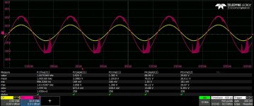
Looks like output stage parasitic oscillation. I doubt more bulk capacitance will remedy that.It seems that 4 x 10000 uF per rail are not enough to give more than 180 W (continous) on 4 ohm! (mono implementation) I will try to add more filter cap close to the PSU board, to see how much it needs
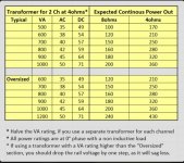
More caps doesn't give you more power. More voltage gives you more power. What size power supply are you running?It seems that 4 x 10000 uF per rail are not enough to give more than 180 W (continous) on 4 ohm! (mono implementation) I will try to add more filter cap close to the PSU board, to see how much it needs
Voltage and VA Rating
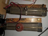
Yes! These are inductors with deliberately increased DC resistance 😉 !
As others yet said, your PSU isn't the first culprit (40 mF filter capacitance per rail is more than sufficient), as isn't the amp itself. You said the supply voltages sag when you observe these oscillations, didn't you? Well, the cause is vice versa: Due to these oscillations the amp draws much more current.
Best regards!
I Agree the power supply is probably not the cause or the oscillation but I believe that the VA rating is a little low.
I've attached a table that my help you.
Are you able to test with another load?
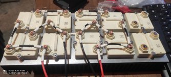
These are the best non inductive resistors.
I've attached a table that my help you.
Are you able to test with another load?
These are the best non inductive resistors.
Attachments
- Home
- Amplifiers
- Solid State
- diyAB Amp The "Honey Badger" build thread