Most probably because it is being used mostly at night with simple girl and guitar music while avoiding hard rock stuff. 🤣...still running with the same 4CW100,000 tube that was installed in 2000. It still has plenty of emission. ...


Nah!, Big Machine idling at 1.2MW and humming happily is the essence of "HEAVY-METAL"

ZM,
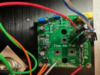
On SB Mu board (non tranny), should C1 be left off?? For some reason I did on my first build but can’t remember why & it works great. Thanks
On SB Mu board (non tranny), should C1 be left off?? For some reason I did on my first build but can’t remember why & it works great. Thanks
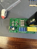
That is a location where you can install a film capacitor to bypass the electrolytic capacitor. The audio signal passes through there so it can be a builder decision. It will work electronically without the bypass capacitor. Some have no doubt put audio grade electrolytic cap in position C2 also. 🙂
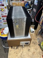
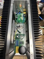
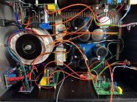
First one up & running…second one in progress
Attachments


Looking good Monk. I too am at the point of firing up the first channel and unfortunately blowing fuses... THF-51S Version
1 - Both channel power supplies fire up fine on a 6.3A SB fuse. 400VA into 66mf-10mH-66mf for each channel. ~68VDC unloaded. Softstart is the store board with default values.
2 - Started SIT board per procedure and everything worked as expected, including adjusting P2.
3 - Connected SIT drain wire, 4A SB fuse in V+ line and turned it on, Iq quickly went up beyond 0.5V across R5/7/9, etc. and before I could click it off, main AC fuse blew.
4 - Double checked Tokin D-S resistance, still 0.9R. Resistance across R1&P1 on Mu board is ~18K.
Will get some better pictures posted, but any recommendations on initial troubleshooting? Thanks!
Attachments
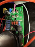
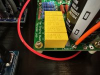
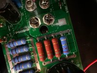
Thanks ZM. no rush. More pics attached, realize I need to flow solder to top side of resistor leads when zoomed in here.
Attachments
-
 IMG_4876.jpg454 KB · Views: 139
 -
 IMG_4874.jpg505.8 KB · Views: 123
 -
 IMG_4873.jpg557.1 KB · Views: 127
 -
 IMG_4875.jpg654.7 KB · Views: 127
 -
 IMG_4872.jpg581.2 KB · Views: 132
 -
 IMG_4871.jpg697 KB · Views: 118
 -
 IMG_4870.jpg770.3 KB · Views: 124
 -
 IMG_4869.jpg795 KB · Views: 131
 -
 IMG_4865.jpg749.3 KB · Views: 142
 -
 IMG_4868.jpg890.5 KB · Views: 147
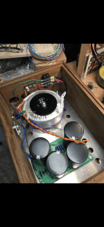
Thanks ZM. no rush. More pics attached, realize I need to flow solder to top side of resistor leads when zoomed in here.
heck
need to rush again
will study later tonight and reply properly ( I hope)
Thanks, whenever you have some time, appreciated. In another development, and because I like to blow fuses, hooked up the other channel and exact same behavior as first channel. Good to see Monk’s up and running looks like the same PS boards.heck
need to rush again
will study later tonight and reply properly ( I hope)
Thanks ZM. no rush. More pics attached, realize I need to flow solder to top side of resistor leads when zoomed in here.
usual drill - check positioning of all zeners, also resistors , also optocoupler ....... even if I can't see anything wrong on pics
now, if you don't find anything wrong with that, you need to commence few tests
did you read this one : https://www.diyaudio.com/community/threads/the-singing-bush-tips-n-tricks.357497/post-6290565
Thanks - yes read and followed the start up tests, no issues at all with the SIT board start up. Checked all resistors and zeners, optocoupler in correct orientation as well... puzzled. Will do more tomorrow night with fresher eyes.usual drill - check positioning of all zeners, also resistors , also optocoupler ....... even if I can't see anything wrong on pics
now, if you don't find anything wrong with that, you need to commence few tests
did you read this one : https://www.diyaudio.com/community/threads/the-singing-bush-tips-n-tricks.357497/post-6290565
just in case, try to ogle back side of Mu pcb , that you didn't left some leftover pins
logic is - whatever happens, current must be limited with Mu follower Iq setting
and now is puzzle why that is not the case
logic is - whatever happens, current must be limited with Mu follower Iq setting
and now is puzzle why that is not the case
- Home
- Amplifiers
- Pass Labs
- The Singing Bush