OK. You're probably trying to tell me that the error is small and that's fine too, but the error is methodical and when people look at your formula they don't understand where you got it at all and what it means. He didn't allow himself to do this, his calculations are accurate. I don't understand how someone can argue with a person who is careless about details and inconsistent? Let's then generally "by eye" figure out why we need formulas...
OK. You're probably trying to tell me that the error is small and that's fine too, but the error is methodical and when people look at your formula they don't understand where you got it at all and what it means. He didn't allow himself to do this, his calculations are accurate. I don't understand how someone can argue with a person who is careless about details and inconsistent? Let's then generally "by eye" figure out why we need formulas...
Yes, I was wrong for not putting the ~ sign in the simplified formula.
I'm just trying to convey information what should be the signal propagation delay to fulfill the Hafler criterion SWDT at a frequency of 10 kHz (-60 dB)
fagos, well, calculate with cosmic accuracy according to the refined formulas what it (tPD) should be
In fairness, it is worth noting that a capacitive load can still occur in real life.
capacitive load and the capacitive nature of the load impedance are not the same thing. The stability of the system is still determined by the capacitive nature of the load impedance, since in fact few reference loudspeakers are used by audiophiles, apparently due to their low sensitivity.
More progressive audio gurus have long ago determined that with a negative feedback depth of more than 60dB at a frequency of 20kHz, the frequency of the first pole no longer matters.Audio-Talib Otala came to the conclusion that the frequency of the first pole should be above the audio range.
Hennady, whatever you call it, but the capacity for the ground in the separation filter may be, I gave a very specific example. Who is the author, you can guess or find yourself, if there is a desire, at least I will tell you in a personal message. And with such filters, not all amplifiers will be able to behave appropriately. But, of course, this is an exception to the rule rather than the rule itself. But we don't like such surprises and try to avoid them, right? 😉capacitive load and the capacitive nature of the load impedance are not the same thing. The stability of the system is still determined by the capacitive nature of the load impedance, since in fact few reference loudspeakers are used by audiophiles, apparently due to their low sensitivity.
Why should I do this? You can figure it out for yourself if you want. The question was in the formula itself and the methodological error that you should correct in your calculations and not carry on. The more precisely you state your theory, the more substantive and constructive the dispute. And when the formula does not understand where it came from, then there is no trust in it and it cannot be used as a reference. That was the whole point of my pointing out the mistake. I've pointed this out before, but you just missed it.fagos, well, calculate with cosmic accuracy according to the refined formulas what it (tPD) should be
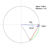
I think that in this case it is necessary to clarify something like this: "The vector error in the range of 20Hz - 20kHz should not exceed -60dB." And in this form, we will already be talking about a limited frequency range and a vector error corresponding to this range. And out-of-band signals don't interest us so much anymore. And in the context of this, my request for your comment about the picture got me, because in his interpretation the wording is about the same - increasing the loop gain in a certain frequency range reduces the vector error in this range.I'm just trying to convey information what should be the signal propagation delay to fulfill the Hafler criterion SWDT at a frequency of 10 kHz (-60 dB)
Limiting the range is logical, since our load also has its own inertial properties and cannot oscillate at frequencies below 1 MHz independently, without an external stimulus (in fact, like a passive resonant circuit in the form of a filter). Therefore, if we do not send a stimulating signal to it at its resonant frequency, it does not spoil our life and everyone is happy.
An amplifier in which the output stage will operate in linear mode can easily cope with such a speaker system filter, in other cases it will be necessary to use a RL circuit.Hennady, whatever you call it, but the capacity for the ground in the separation filter may be, I gave a very specific example. Who is the author, you can guess or find yourself, if there is a desire, at least I will tell you in a personal message. And with such filters, not all amplifiers will be able to behave appropriately.
A big negative for the sound in the amplifier comes from the weak gain of the input stages and their linearity - the rest is a matter of topological design ...But, of course, this is an exception to the rule rather than the rule itself. But we don't like such surprises and try to avoid them, right?
Hennady, if we correct with the dominant pole and make the decline in the first order, being content with the scanty depth of loop amplification at high frequencies, then we will certainly have the opportunity to work on capacity without complexity. But how much can we get then? 40-45dB maximum? And if there is no filter, then for stability you will have to sacrifice even more loop gain and 25dB will remain to achieve the same phase margin. This is clearly not our method. Yes, and you yourself put the output filter in your products, I remember. And not so long ago, in February, you even wrote a post about the output filter on another forum, so you have already studied the topic and have an idea. I think we'll finish this and wait for the message from petr_2009.
in this case, the maximum will be 30dB.Hennady, if we correct with the dominant pole and make the decline in the first order, being content with the scanty depth of loop amplification at high frequencies, then we will certainly have the opportunity to work on capacity without complexity. But how much can we get then? 40-45dB maximum?
right! it is still necessary to transfer the output stage to a more linear mode and this is not always a sufficient condition for obtaining the stability of the transient responseAnd if there is no filter, then for stability you will have to sacrifice even more loop gain and 25dB will remain to achieve the same phase margin.
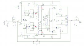
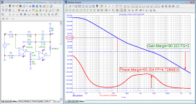
I modeled his version, just threw out the input stage on Jfet and changed the laterals to the normal Lokanti output stage - and of course it turns out better, because. more linear amplification of the input part, the output operating point is well balanced by DC (1mV). The depth of negative feedback at a frequency of 20kHz is 71dB, the pole is 13.5kHz, but the correction will need to be finalized.and wait for the message from petr_2009.
a simplified formula is given for use in the audio range (geometry for the 5th grade of elementary school). The maximum error in the audio range is only at the highest frequency of 20 kHz. In the rest of the sound range, and even more so, the error can be neglected.The question was in the formula itself and the methodological error that you should correct in your calculations and not carry on. The more precisely you state your theory,
Attachments
petr_2009,I repeat once again - the question is not in the accuracy of calculations, but in the correct formula that conveys the physical essence and its mathematical representation. Since you have taken to using vector visualization methods, then do it correctly so that others can check the correctness of your conclusions. And if everyone wants to write formulas as he wants, then what can we argue about at all and what will be the basis? The scientific approach must be followed.
fagos, I made another mistake: I used the number 3.14 instead of 3.1415926535897932384626433832795… So take this into account when calculating.

The point is not in the accuracy of calculations, but in the reflection of the meaning of the formula. OK, I get it - my formula is too complicated for you. You can use at least chopsticks for counting, because everyone chooses an instrument according to their level. If, after repeating it several times, I could not convey to your understanding what the essence of the claims to the formula is, then it is not worth talking about more complex things.fagos, I made another mistake: I used the number 3.14 instead of 3.1415926535897932384626433832795… So take this into account when calculating.
Hennady, do you think 70 dB loop gain is enough for high quality audio amplification?More progressive audio gurus have long ago determined that with a negative feedback depth of more than 60dB at a frequency of 20kHz, the frequency of the first pole no longer matters.
fagos, well, calculate with cosmic accuracy according to the refined formulas what it (tPD) should be (262)
Attachments
Last edited:
just like the Sandy amplifierOK, but what's that got to do with Apex A40, Mile Slavkovic?
in fact, many have a different understanding of this very quality. The figure 60dB is not taken from the ceiling, with a single-stage topology, the maximum gain rarely exceeds 90dB, minus the gain of 24-26dB and 4-6dB of losses used for gain linearity, it remains just 60dB, This value can be less if the gain is linear in the audio frequency band up to negative feedback coverage.Hennady, do you think 70 dB loop gain is enough for high quality audio amplification?
With a two-stage topology, it is theoretically possible to obtain a gain of 180 dB, but in fact, it is very difficult to obtain a gain of more than 110 dB without lowering the pole, because the unity gain frequency is already striving to jump beyond the frequency of 10 MHz, i.e. limit of the technological possibility of the radio amateur level.
also with increasing gain, it is necessary to correct with circuits of higher orders, for the first order of correction, which I very often see in your models, you can forget - its problem at a certain depth at a frequency of 20kHz, at which the pole cannot be higher than 20kHz, or it will be an amplifier with very low gain (45-55db) to negative feedback coverage.
super high quality - this is a negative feedback depth of at least 90db at a frequency of 20kHz. Will there be a high quality amplifier with 70dB negative feedback at 20kHz? yes, it will.
what's that got to do with Apex A40, Mile Slavkovic?
If we compare them topologically, then Slavkovich has an input stage with tracking power, Sandy removed it, increasing the feedback depth and, as a result, reducing distortion.just like the Sandy amplifier
How this can affect the quality of sound reproduction - I think in no way. because both Slavkovich and Sandy's input stage in fact turns out to be a follower with a very low input impedance for a negative feedback signal, i.e. cascades do not amplify anything at the input.
But Slavkovich's option is preferable, because. the option of tracking the input sound signal gives, in fact, a more comfortable sound.
- Home
- Amplifiers
- Solid State
- Apex A40 fundamental improvement. (Sandy)