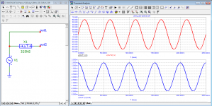
A phase shift of 45 degrees for a frequency of 1KHz equals a delay of 1mS/8= 125uS.
And only idiots don't understand that it's the same thing measured by different units of measurement
In some calculations it is more convenient to work with angles, in others with times.
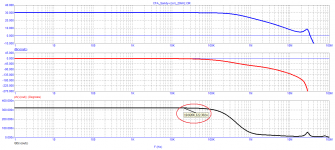
Well, your group delay time is shown in an even larger range of 10Hz-10MHz
And you can see for yourself in the picture how much it is at 20Hz and at 20KHz
If you can write, even if it's just nonsense, then you're not blind.
And only idiots don't understand that it's the same thing measured by different units of measurement
In some calculations it is more convenient to work with angles, in others with times.
Well, your group delay time is shown in an even larger range of 10Hz-10MHz
And you can see for yourself in the picture how much it is at 20Hz and at 20KHz
If you can write, even if it's just nonsense, then you're not blind.
Sandy, you're avoiding a straight answer again.
I ask you to give only 4 numbers with an accuracy of up to a nanosecond (+ -2%).
Or do you lack the intelligence (as you always say to me) to make elementary measurements?
This is equivalent to if I asked you to measure the distance to the moon, and you tell me that you do not have enough tape measure.
A simulator in the hands of people without logical thinking is as useful as a grenade is in the hands of a monkey.
Sandy, here's a help (prompt) for you.
This is how monkeys or the Taliban do it with a grenade at 20 kHz
And endure your move (step) - show the result of measurements at a frequency of 20 Hz
as you can see in both cases 322 ns
Attachments
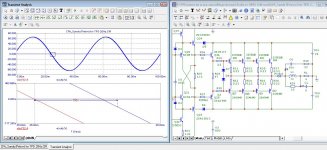
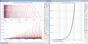
Here comes tPD
20Hz tPD=84.356nS
20KHz tPD=80.59nS
Naturally only 4 times better than your current amplifier. 😢😉
Naturally, these parameters mean nothing for an audio amplifier.
But the Taliban naturally has no way of understanding this, but a monkey would.
20Hz tPD=84.356nS
20KHz tPD=80.59nS
Naturally only 4 times better than your current amplifier. 😢😉
Naturally, these parameters mean nothing for an audio amplifier.
But the Taliban naturally has no way of understanding this, but a monkey would.
Attachments
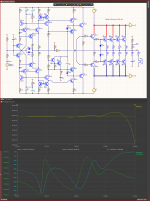
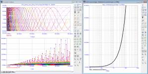
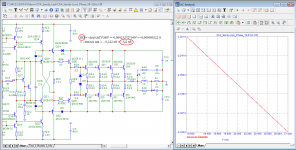
1.Sandy, you have removed the output inductance, but your amplifier model is inoperable without it (I suspect that you do not know how it is determined, see the figure).
2. You argued with me for a long time that the group delay and the signal delay time have nothing in common. But even with crooked measurements, it can be seen that the values are close. Why? I already explained to you in the telegram channel. Let me remind you: in areas where the frequency response and phase response are linear.
3. In my measurements with a 1 uH inductance, all four numbers match to within 1 ns!
Attachments
Well, I understand that a person with the intelligence of an amoeba is difficult to understand that, an input filter, an amplifier, and an output filter for 3 different things.
And accordingly they must be studied separately to know their influence.
If we care about the input filter, we look at the input filter.
If we are interested in the amplifier, we look at the amplifier.
If we are interested in the output filter, we look at it.
You look at both your amplifiers and mine as you see fit to manipulate the result according to your stupid criteria.
I showed you how by reworking the frequency correction the amplifier can work with a capacitive load and no inductance in the output.
At the end, say with what input and output filter you want the amplifier to be.
I can do it with any, because unlike you, I can calculate without a simulator.
But if we are going to compare 2 amplifiers, we should compare them either with the same input and output filters, or preferably without them.
You never answer specific questions, because either you don't understand them, or you are afraid that you will expose yourself again.
I asked you simple questions!!
Do you distinguish between a delay caused by an RC circuit and a delay caused by a delay line.
Apparently you do not make such a distinction, which shows total technical illiteracy on the subject.
I asked you simple questions!!
What is the quiescent current of the MOS transistors to do the same on my amplifier and show you its distortions at the same output voltage.
You don't answer because you know you'll be laughed at again.
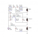
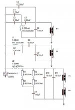
Here is work with a real speaker as a load and without inductance in the output.
Only an idiot would think that a speaker can have 8uF capacitance as a load.
And this is a problem for him, for his GP, and also for the rest of the fans (idiots) who believe in such legends.
************************************************************************
.SUBCKT SPEAKER-4 G $N_0002
R_R29 $N_0002 $N_0001 4
R_R30 $N_0003 $N_0002 2.5
R_R31 $N_0004 $N_0002 2.8
C_C9 $N_0001 $N_0005 9.4uf
C_C10 G $N_0003 6.6uf
R_R32 $N_0006 $N_0005 0.25
L_L16 $N_0004 $N_0007 0.25mH
R_R33 $N_0009 $N_0008 50
R_R34 $N_0008 G 19.5
R_R35 $N_0008 $N_0010 0.3
R_R36 $N_0008 $N_0011 0.45
L_L17 $N_0011 $N_0009 0.5mH
L_L18 G $N_0010 5mH
R_R37 $N_0009 $N_0007 0.35
L_L19 G $N_0006 0.15mH
C_C11 G $N_0008 1mf
.ENDS
************************************************************************
.SUBCKT SPEAKER-8 G $N_0002
R_R29 $N_0002 $N_0001 8
R_R30 $N_0003 $N_0002 5
R_R31 $N_0004 $N_0002 5.6
C_C9 $N_0001 $N_0005 4.7uf
C_C10 G $N_0003 3.3uf
R_R32 $N_0006 $N_0005 0.5
L_L16 $N_0004 $N_0007 0.5mH
R_R33 $N_0009 $N_0008 100
R_R34 $N_0008 G 39
R_R35 $N_0008 $N_0010 0.6
R_R36 $N_0008 $N_0011 0.9
L_L17 $N_0011 $N_0009 1mH
L_L18 G $N_0010 10mH
R_R37 $N_0009 $N_0007 0.7
L_L19 G $N_0006 0.3mH
C_C11 G $N_0008 500uf
.ENDS
*-----------------------------------------------------------------------
Only an idiot would think that a speaker can have 8uF capacitance as a load.
And this is a problem for him, for his GP, and also for the rest of the fans (idiots) who believe in such legends.
************************************************************************
- generic speaker simulation (4 ohm)
- as published in Stereophile Magazine.
- Donated by Jaime Arbona, converted to subcircuit form
.SUBCKT SPEAKER-4 G $N_0002
R_R29 $N_0002 $N_0001 4
R_R30 $N_0003 $N_0002 2.5
R_R31 $N_0004 $N_0002 2.8
C_C9 $N_0001 $N_0005 9.4uf
C_C10 G $N_0003 6.6uf
R_R32 $N_0006 $N_0005 0.25
L_L16 $N_0004 $N_0007 0.25mH
R_R33 $N_0009 $N_0008 50
R_R34 $N_0008 G 19.5
R_R35 $N_0008 $N_0010 0.3
R_R36 $N_0008 $N_0011 0.45
L_L17 $N_0011 $N_0009 0.5mH
L_L18 G $N_0010 5mH
R_R37 $N_0009 $N_0007 0.35
L_L19 G $N_0006 0.15mH
C_C11 G $N_0008 1mf
.ENDS
************************************************************************
- generic speaker simulation (8 ohm)
- as published in Stereophile Magazine.
- Donated by Jaime Arbona, converted to subcircuit form
.SUBCKT SPEAKER-8 G $N_0002
R_R29 $N_0002 $N_0001 8
R_R30 $N_0003 $N_0002 5
R_R31 $N_0004 $N_0002 5.6
C_C9 $N_0001 $N_0005 4.7uf
C_C10 G $N_0003 3.3uf
R_R32 $N_0006 $N_0005 0.5
L_L16 $N_0004 $N_0007 0.5mH
R_R33 $N_0009 $N_0008 100
R_R34 $N_0008 G 39
R_R35 $N_0008 $N_0010 0.6
R_R36 $N_0008 $N_0011 0.9
L_L17 $N_0011 $N_0009 1mH
L_L18 G $N_0010 10mH
R_R37 $N_0009 $N_0007 0.7
L_L19 G $N_0006 0.3mH
C_C11 G $N_0008 500uf
.ENDS
*-----------------------------------------------------------------------
Attachments
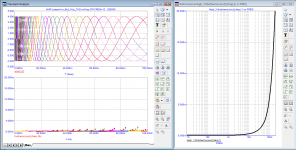
Have you checked? Show the result. Why did they show only 20kHz themselves?And endure your move (step) - show the result of measurements at a frequency of 20 Hz
as you can see in both cases 322 ns
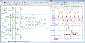
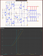
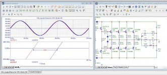
Since you prefer to ignore my messages, you can not reply and continue this. But I will show my pictures based on your model to exclude all discrepancies. And as a result, at 20Hz, the graphs are shifted by 120ns, not 320ns. And at the same time I attach a graph of the group delay time from the AC analysis for comparison. Think about it.
P.S.Since the meter works according to the calculated points, it was not possible to establish exactly and in the picture it covered a wider area, but manual measurement gives 120ns.
Attachments
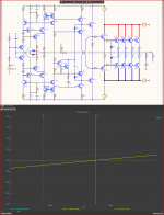
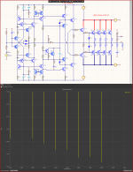
In fairness, it is worth noting that a capacitive load can still occur in real life. I saw one such example (I would not like to name the author) and was shocked. I can say that this product is amateur, but it is possible to find similar examples in a professional environment if you search. In the end, I would still not throw out the output filter😉Here is work with a real speaker as a load and without inductance in the output.
Only an idiot would think that a speaker can have 8uF capacitance as a load.
And this is a problem for him, for his GP, and also for the rest of the fans (idiots) who believe in such legends.
If you look at the circuits, you can see the paths of current flowing through the capacitances to the ground. It's certainly not 8uF, but it's still significant.
Attachments
The problems come from the fact that people with little experience and even negative technical knowledge try to make filters not by knowledge but by guesswork.
And the results are usually deplorable.
Capacitance that can lead to self-excitation is mostly on the long cable to the column.
And the RL circuit at the output of the amplifier is enough to solve the problem.
The problem with stupidly made filters in the column itself is already on the conscience of the authors.

Tech-illiterate audio-Talibans like you and Otala are flying in the clouds of audiophile insanity.
And he doesn't know what feedback is and how it works.
Audio-Talib Otala came to the conclusion that the frequency of the first pole should be above the audio range. Unlike you, Otala perfectly understood that the loop gain drops above the frequency of the first pole, the loop gain is phase-shifted up to 90 degrees, which contributes to the growth of not only non-linear distortions, but also temporary ones.
Attachments
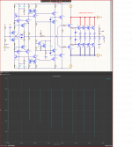
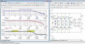
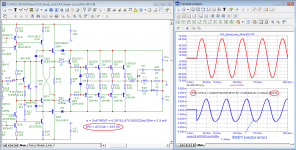
Sandy, take into account how to measure tPD using Jiri Dostal's formulas so as not to apply a voltage of 20 V to the input of the amplifier! And at the same time have large measurement errors.
As you can see, the measurement error is within 1 ns.
To accurately measure all types of distortions by the compensation method, it is sometimes necessary to measure tPD with an accuracy of fractions of a ns.
As you can see, the measurement error is within 1 ns.
To accurately measure all types of distortions by the compensation method, it is sometimes necessary to measure tPD with an accuracy of fractions of a ns.
Attachments
We have already discussed Otala and established that he is an idiot who does not understand anything about electronics.
And those who believe him are even bigger idiots.
For people like you who are deprived of the ability to think logically, it is harmful to read, because they do not understand what they read and it becomes a big mess in their head.
The LR filter after the amplifier just puts in a linear curve cutting off the high frequencies.
And especially in the simulator it cannot introduce non-linear distortion because L there is an ideal inductance.
GD and tPD are directly related to the amplitude-frequency response of an amplifier or RC (LR) circuit.
And in Dostal's book there are formulas with which one can go from one to the other.
But this knowledge is unavailable to you.
And only a masochist and idiot works with the more difficult to work with GD and tPD.
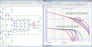
Upload a diagram executed according to the ideas of the idiot Otala
And I will upload my scheme with first pole 10-100Hz which will distort at least 10 times a bit.
I am still waiting for an answer to the question Is Out1 Out2 the same????
And those who believe him are even bigger idiots.
For people like you who are deprived of the ability to think logically, it is harmful to read, because they do not understand what they read and it becomes a big mess in their head.
The LR filter after the amplifier just puts in a linear curve cutting off the high frequencies.
And especially in the simulator it cannot introduce non-linear distortion because L there is an ideal inductance.
GD and tPD are directly related to the amplitude-frequency response of an amplifier or RC (LR) circuit.
And in Dostal's book there are formulas with which one can go from one to the other.
But this knowledge is unavailable to you.
And only a masochist and idiot works with the more difficult to work with GD and tPD.
Upload a diagram executed according to the ideas of the idiot Otala
And I will upload my scheme with first pole 10-100Hz which will distort at least 10 times a bit.
I am still waiting for an answer to the question Is Out1 Out2 the same????
Attachments
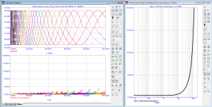
Great. Of course, I understand that my words are inconvenient, but why did petr_2009 change the method for determining the delay time? First, he drew the input and output signal and directly offered to estimate the distance between them, and now for some reason he offers to calculate them indirectly by the magnitude of the error.As you can see, the measurement error is within 1 ns.
To accurately measure all types of distortions by the compensation method, it is sometimes necessary to measure tPD with an accuracy of fractions of a ns.
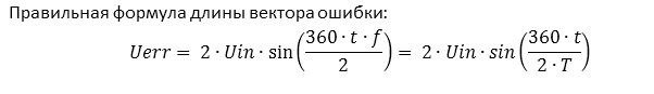
And besides, even despite my repeated indications that the formula is incorrect, it is still not fixed. The formula petr_2009 with an increase in the phase deviation gives an increasing calculation error, but it is still persistently used and given as a reference material. Where is the logic here?
We have already discussed Otala and established that he is an idiot who does not understand anything about electronics.
And those who believe him are even bigger idiots.
For people like you who are deprived of the ability to think logically, it is harmful to read, because they do not understand what they read and it becomes a big mess in their head.
The LR filter after the amplifier just puts in a linear curve cutting off the high frequencies.
And especially in the simulator it cannot introduce non-linear distortion because L there is an ideal inductance.
GD and tPD are directly related to the amplitude-frequency response of an amplifier or RC (LR) circuit.
And in Dostal's book there are formulas with which one can go from one to the other.
But this knowledge is unavailable to you.
I am still waiting for an answer to the question Is Out1 Out2 the same????
Sandy, I was convinced that it is useless to explain anything to you, anyway you will remain with your convictions.
Instead of training on simple RC elements, dial two models of speaker cables 8 meters long with the same active resistance.
One model with the maximum linear inductance.
The second - with the maximum linear capacito.
Take the parameters of both cables and tell me how they will sound in a good system with a reference amplifier and reference acoustics.
Then turn to forum visitors with a request to confirm your conclusions.
I hope I find these.
Then you will draw conclusions on what passive RCL elements in the audio path influence or do not influence
fagos, prove that the formula is wrong. It is taken from the book DostalAnd besides, even despite my repeated indications that the formula is incorrect, it is still not fixed. The formula petr_2009 with an increase in the phase deviation gives an increasing calculation error, but it is still persistently used and given as a reference material. Where is the logic here?
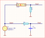
It's not worth redirecting arrows to him, trying to slip through on his authority - this is not his mistake, but yours. Here is a link to your drawing with the calculation formula:
https://www.diyaudio.com/community/attachments/cfa_sandy-cor-_20hz_tpd-png.1101830/
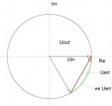
And now look at Figure 1 in the attachment, which illustrates what the error is. You determine the length of the circle sector between the input and output voltage vectors, but the difference is equal to the vector, not the circle sector. Therefore, the correct calculation formula (the chords of the circle in this case) is shown in Figure 2.
If you have seen your version of the formula in the book Jiri Dostal, then give the number of the formula or page, I did not find it.
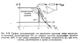
As a separate question, I can cite a curious drawing from the book that I would like to show you and ask for a comment on this. As you understand, in the context of your theory, I got the statements in the caption to the drawing. Since the drawing is from the Russian-language version (fig.3), then for the English-speaking audience I bring in addition the same one from the English-language edition (fig.4).
I will explain why I ask the question - the vector error at the F1 frequency will decrease, but petr-2009 shows us on the contrary an increase in the vector error with an increase in the depth of feedback. Got's statements correspond to the classical theory, and petr_2009, referring to him, contradicts him. It turns out some kind of incident that requires resolution and clarification.
https://www.diyaudio.com/community/attachments/cfa_sandy-cor-_20hz_tpd-png.1101830/
And now look at Figure 1 in the attachment, which illustrates what the error is. You determine the length of the circle sector between the input and output voltage vectors, but the difference is equal to the vector, not the circle sector. Therefore, the correct calculation formula (the chords of the circle in this case) is shown in Figure 2.
If you have seen your version of the formula in the book Jiri Dostal, then give the number of the formula or page, I did not find it.
As a separate question, I can cite a curious drawing from the book that I would like to show you and ask for a comment on this. As you understand, in the context of your theory, I got the statements in the caption to the drawing. Since the drawing is from the Russian-language version (fig.3), then for the English-speaking audience I bring in addition the same one from the English-language edition (fig.4).
I will explain why I ask the question - the vector error at the F1 frequency will decrease, but petr-2009 shows us on the contrary an increase in the vector error with an increase in the depth of feedback. Got's statements correspond to the classical theory, and petr_2009, referring to him, contradicts him. It turns out some kind of incident that requires resolution and clarification.
Attachments

- Home
- Amplifiers
- Solid State
- Apex A40 fundamental improvement. (Sandy)