I have such a result so far
such results with such a topology, I want to hug and cry....
Your results are not a reason to make claims to Sandy Todorov.
I have no complaints, but the simulation of the Sandy variant showed the same result in general terms as Petrka ... Therefore, I will model the A40 to understand how bad everything is ...
petr_2009
Sandy has always sat firmly on the ground.
Tech-illiterate audio-Talibans like you and Otala are flying in the clouds of audiophile insanity.
Otala, like you, has no concept of electronics.
And he doesn't know what feedback is and how it works.
Sandy has always sat firmly on the ground.
Tech-illiterate audio-Talibans like you and Otala are flying in the clouds of audiophile insanity.
Otala, like you, has no concept of electronics.
And he doesn't know what feedback is and how it works.
 Please see forum RULE #1 Personal remarks and insults are not allowed here. Keep it civil, keep it respectful.
Yes, you're right, I didn't see the model.you are inattentive, the model is in the archive
https://www.diyaudio.com/community/...amental-improvement-sandy.346751/post-7139288
p.s.
post your model
Maybe later. First I want to compare myself and look for the reasons. Of course, it will be a matter of models, but we need to be consistent and determine the impact. I will report the results here later.
As a report to the community. I compared the models and understood why there was a difference in the results.First I want to compare myself and look for the reasons. Of course, it will be a matter of models, but we need to be consistent and determine the impact. I will report the results here later.
1) I used other component models in my file. Your models seem more than acceptable to me, so I decided to build on them. The replacement did not completely solve the problem, I started an element-by-element comparison.
2) The results as you get after bringing the frequency compensation to your option - 20pF + 10 ohms. And I initially measured with the standard correction from Sandy, which showed a normal result with my models. In your case, the need to tighten the frequency compensation reduces the loop gain and distortion naturally increases.
As a result, I consider this issue resolved.
Sandy, learn to test your developments, don't get hung up on measuring only THD.
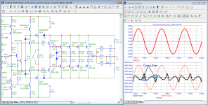
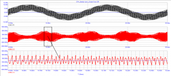
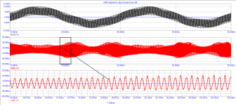
Here are the results of measuring distortion at 10 kHz with an output voltage of 4 V (peak). Switching distortion measured on a composite signal 100 Hz + 20 kHz.
It can be seen with the naked eye that the amplifier with field-effect transistors (the frequency of the first pole is 30 kHz) introduces softer distortions.
Attachments
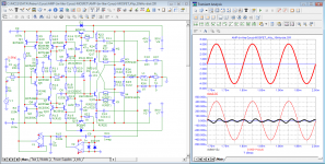
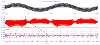
in a model with output transistors of the Lateral type, distortion is an order of magnitude lower
gave references to literature sources
gave references to literature sources
Attachments

Last edited:
The variants of the Sandu and petr circuits are completely different, and have different output impedances of the drivers and different widths of the frequency spectrum when controlling the transistors of the output stage.
Crossover distortion for which petr pushes is beyond the audiophile's hearing range and affects the sound quality at this level only in the imagination of the circuit topology designer.
It is also completely incomprehensible that petr desire to make a current topology for controlling mosfets, both horizontal and, oh my God, vertical !!!
In this case, the simulation result will not correspond to the practically implemented scheme.
Well, petr_2009 can't answer any question in a meaningful ...
Sandy, answer meaningfully to one question: what are the Group Delay and tPD in your amplifier model at a frequency of 20 Hz and 20 kHz And if they are different, then why?
p.s.
second indiscreet question: so what point in the circuit contacts the output terminals of the amplifier, what is really the output?
I am completely illiterate in the field of medicine.
And I'm not offended if someone tells me that, because I know it's true.
But if I brazenly start giving the doctors advice on how to treat, they have every right to consider me an idiot.
You're right, Sandy, if a proctologist starts advising a surgeon on how to do heart surgery, the surgeon will most likely think he's an idiot. So here - you have no idea about the state of affairs in audio development, but you are trying to give advice.
I try to give advice in the field of electronics because I am > 50 years old. experience as a constructor in almost all areas.
And especially in military electronics.
It is pointless to give advice to people like you without basic minimal knowledge in this area.
You make up false experimental setups, get wrong results and make up non-existent problems.
There are only 2 types of distortion, linear (amplitude frequency response) and non-linear (THD).
You keep confusing distortion measurement methods with distortion itself.
Only a very illiterate technical person can think that with MOS final transistors he can get as little THD as with BJT.
And this is proven for 2 imnuti accounts with a pencil on a piece of paper.
But this is a hyper-intellectual effort for people like you who have no idea what this distortion is and what causes it.
How much is the quiescent current through the MOS transistor of the allegedly slightly distorting amplifier.
If you dare, run the same current through the BJT final stage and then compare the distorted one.
To manipulate things in this way is not complicated.
But I don't think you're trying to lie to us.
You don't have enough knowledge to do it.
You just pulled a random result that you don't understand where it came from.
Last edited:
Sandy, answer essentially the question posed, or do you not have enough knowledge for this?Sandy, answer meaningfully to one question: what are the Group Delay and tPD in your amplifier model at a frequency of 20 Hz and 20 kHz And if they are different, then why?
p.s.
second indiscreet question: so what point in the circuit contacts the output terminals of the amplifier, what is really the output?
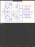
Here's your group lag time.
Define what you understand by tPD so that I can answer this question as well.
All amplifiers with the same bandwidth have the same group delay time.
Of course, this is incomprehensible to people like you. 😉
Sandy, you stubbornly evade the answer to the question: from what point in the circuit does the signal enter the output terminals of the amplifier? Or you will recommend to audio experts like Stereophile to open up your amplifier and check the specifications before the inductance in order to deceive potential buyers.
As for your test, you again removed the Group Delay characteristic before the inductance, and not at the output of the amplifier.
The signal delay time is the Dostal time shift. See drawing.
Attachments
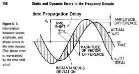
Only extremely gifted morons don't understand that there is no difference between delay time and phase shift.
Yes, you can express the same thing both as time and as phase angle.
But it always remains the same physical phenomenon.
The amplifier we are interested in as parameters is the thing covered by common feedback.
And before it and after it you can put 10 more filters.
And accordingly, you will radically change the parameters of this already different system.
And only a moron would attempt to compare amplifiers with different input and output filters.
These are some of your conjectures that you are trying to attribute to another person in order to make him look bad. This is unworthy behavior, you don't need to do that.Sandy, you stubbornly evade the answer to the question: from what point in the circuit does the signal enter the output terminals of the amplifier? Or you will recommend to audio experts like Stereophile to open up your amplifier and check the specifications before the inductance in order to deceive potential buyers.
And according to the facts, you use a group delay time in order to characterize the "speed" of the feedback loop, although this is not canonical. Let's say we want to listen to your arguments and you have to remove some characteristics to convince us. It would be quite logical to look at the point where the feedback signal comes from, and not after the filter. But you have mixed the "canonical" and "non-canonical" meanings into one pile and suggest that we evaluate after the filter, although there is no feedback there anymore, but there is a filter reaction. Where is the logic? This no longer characterizes the feedback loop, even according to your "non-canonical" methods.
In addition, if we completely abandon the output filter, following your advice, then we need to tighten the nuts of frequency compensation so that the stability reserves are gigantic. As a result, this leads us to the fact that we cannot make much feedback at high frequencies and, accordingly, have to settle for 40 dB at a maximum of 20 kHz, and this is not enough to effectively suppress distortion and achieve really high linearity, whatever the simulator shows you.
The second way is to install a filter. This allows us to maximize the gain available to us to reduce distortion, while the influence of load capacity can draw us creepy pictures when a step signal is applied, but in fact this is just a filter reaction to this signal and has nothing to do with the instability of the amplifier. And if we are afraid of these pictures and do not understand what it is, then we can certainly slide into the abyss. But logic tells us that if the output filter with a capacitor in the load is not stimulated by a step signal containing the resonance frequency of the filter in the spectrum, then there will be no such reaction, and therefore there is nothing to be afraid of. Based on this, we put an input filter at the input of the amplifier that limits the frequency band and get an excellent result.
You have been told more than once that you should not use group delay time as a measure of feedback speed, but you are stubborn and do not understand that this leads to confusion. It's like hammering screws - in principle, you can, but there are tools for screws, but you stubbornly ignore them and continue to work with a hammer.
Only extremely gifted morons don't understand that there is no difference between delay time and phase shift.
Sandy, firstly, you constantly confuse different concepts: phase is degrees, Group Delay is time.
Secondly, lead me by the nose, you beat around the bush, instead of answering a simple question meaningfully from the height of your intellect:
what is the Group Delay and tPD in your amp model at 20Hz and 20kHz in nanoseconds
you only need 4 numbers (numeric)!
To facilitate the task, I even supplemented your document with calculations.
https://www.diyaudio.com/community/...amental-improvement-sandy.346751/post-7149472
Last edited:
- Home
- Amplifiers
- Solid State
- Apex A40 fundamental improvement. (Sandy)