Petrik, when did you manage to become a developer of amplifiers? As far as I remember, if you really are that Petrik, you were always a theorist, and your understanding of the main parameters for the practical implementation of the amplifier was always very far from practical implementations, because obviously you never soldered the amplifier yourself. And your topologies, borrowed solutions of real masters of this business, as well as theoretical calculations, with certain compilations, can really have good parameters in the model, but why break away from practical implementation.Hennady, are you involved in the design of amplifiers? The question arose because you are talking about the performance of the amplifier according to the signs by which the developers not judge.
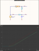
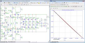
Another nonsense ... Let me not specify the reasons ...Here is a graph of the loop gain with additional reactive load. What does this chart tell you?
I don’t play such “games” with modeling magicians ...
I modeled a couple of your (or not your) topologies and they were not all properly adjusted. I even tried only your "typology of undercorrection" a couple of times to get the minimum group delay - as a result, it all sounded disgusting and uncomfortable, which cannot be said about a model where everything seems to look beautiful ...
Here is the difference between real delay (delay line)
And millet limited bandwidth (cutting high frequencies)
With the delay line just in the output 1.6uS nothing changes!!!!
In the RC group, the output starts changing simultaneously with the input. And in that sense, there is no delay.
It's just that the high frequencies responsible for the sharp edge are gone, and then the edge is rounded.
In amplifiers we have the case of the RC circuit.
And to compensate for "delay" caused by an RC circuit with a delay line is idiocy.
A simulator in the hands of people without logical thinking is as useful as a grenade is in the hands of a monkey.
This is how this study should be done and how the phase shift of the signal at the output of the amplifier should be compensated.
The deceleration is compensated by the acceleration circuit C6 R35.
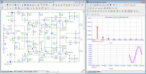
In the first example, the bandwidth of the pulse packet is not limited.
And of course at this point of entry there are also very high frequencies >>MHz
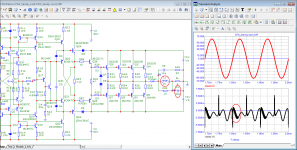
And of course there is a big difference between input and output, the high frequencies at the output of the amplifier are naturally cut off.
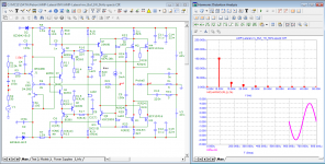
In the second picture THD-100KHz we have already limited the frequencies to 100KHz with the R1C1 circuit
And oh wonder (for illiterate audio designers) the vector error became almost non-existent.
And millet limited bandwidth (cutting high frequencies)
With the delay line just in the output 1.6uS nothing changes!!!!
In the RC group, the output starts changing simultaneously with the input. And in that sense, there is no delay.
It's just that the high frequencies responsible for the sharp edge are gone, and then the edge is rounded.
In amplifiers we have the case of the RC circuit.
And to compensate for "delay" caused by an RC circuit with a delay line is idiocy.
A simulator in the hands of people without logical thinking is as useful as a grenade is in the hands of a monkey.
This is how this study should be done and how the phase shift of the signal at the output of the amplifier should be compensated.
The deceleration is compensated by the acceleration circuit C6 R35.
In the first example, the bandwidth of the pulse packet is not limited.
And of course at this point of entry there are also very high frequencies >>MHz
And of course there is a big difference between input and output, the high frequencies at the output of the amplifier are naturally cut off.
In the second picture THD-100KHz we have already limited the frequencies to 100KHz with the R1C1 circuit
And oh wonder (for illiterate audio designers) the vector error became almost non-existent.
Attachments

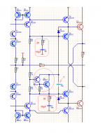
According to the scheme of the author of the topic, I propose to divide the correction chain so that the R22C3 correction does not form a loop for T14 through the T17T18 multiplier. This will be important when clipping in the amplifier, when the internal resistance of the multiplier changes, and the quality of the capacitor C4 will not be enough to shunt these changes at high frequency.In amplifiers we have the case of the RC circuit.
Since the scheme is completely symmetrical complementary, a variant of the Malcolm Hawkford multiplier can be used.(option to consider)
As for the rest of the type of correction, I can comment in more detail when I finish modeling the author's version.
Attachments
I am uploading some literature on the matter.
And even how to make an amplifier with a negative group delay time
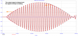
That is, the signal at the output appears before it is applied to the input.
If your personal theory was correct that the group delay time is the time it takes the signal to reach the output.
Sandy, the signal cannot appear before it is entered! How can the amplifier know that it will be given a signal at the input. The advance of the signal appears in the process of its amplification by the amplifier, just like the advance of the signal in the CR chain occurs. I already chewed this example in another thread, but for you personally I will repeat it again
A negative group delay value only means that the output signal envelope will lead the input signal envelope.
Attachments

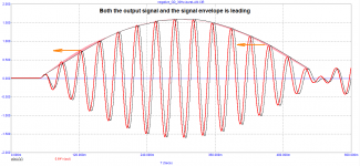
Well of course the signal cannot appear in the output before it is input.
But the group delay time can be negative.
And the corollary to what you can't understand is that the group delay time is not the transit time of the signal through the amplifier.
But arguing with a person devoid of logical thinking and with negative technical knowledge is pointless.
The fact that you compensate for phase delay with a delay line speaks volumes enough that you have no concept of electronics.
Hennady Kovalsky Such division of correction has no practical sense 100nF e 50000 larger than 20pF
Sandy, read your document in Russian, maybe in Russian it will be easier for you to understandWell of course the signal cannot appear in the output before it is input.
But the group delay time can be negative.
And the corollary to what you can't understand is that the group delay time is not the transit time of the signal through the amplifier.
But arguing with a person devoid of logical thinking and with negative technical knowledge is pointless.
The fact that you compensate for phase delay with a delay line speaks volumes enough that you have no concept of electronics.
Attachments

Last edited:
This is understandable, in addition, the 100nF capacitor will technologically be film, and the 20pF capacitor will be ceramic, that is, a different technology.Hennady Kovalsky Such division of correction has no practical sense 100nF e 50000 larger than 20pF
You used a local feedback multiplier, but the fact is that with such a solution at high frequencies near the unity gain frequency, the efficiency of the feedback around the transistor drops, and the resistance of the multiplier becomes inductive. A 100nf capacitor neutralizes this phenomenon.
All the same, I will turn again by proposing a variant of the Malcolm multiplier, because in this case there will be no rigid connection between the output voltage of the multiplier Vbe and its temperature coefficient.
And splitting a RS circuit without a loop through a multiplier in fully complementary circuits has always led to a positive effect, since even the influence of conductors on the printed circuit board was reduced ...
In whatever languages I read the document, it does not change its meaning.
The problem is that you do not understand the point of this document.
The linearity of the phase response is important in frequency and phase modulation.
It doesn't matter about the audio.
When recording, do you have any idea how many EQs the signal goes through and what their group delay times are.
We're arguing about something else entirely and you're trying to get out of it without actually responding.
The issue is whether these dynamic distortions you invented are there or not.
Your dynamic distortions are the result of your technical illiteracy, which is why you can't do a proper simulation.
I'm sorry to say it, but facts are an inexorable thing.
The method of measuring THD by subtraction has been known since before you and I were born.
But you obviously don't understand how this is done.
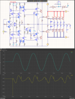
Sorry for uploading the same picture and asking the same question again.
Is there a difference according to Out1 / Out2 yellow / blue ??
Can someone in their right mind compensate for the yellow delay with the blue.
Naturally, then the area enclosed between the two graphs will appear as the notorious "Speed Distortion"
Except that it is not the result of a bad amplifier, but is the result of a technically illiterate experimental setup.
The problem is that you do not understand the point of this document.
The linearity of the phase response is important in frequency and phase modulation.
It doesn't matter about the audio.
When recording, do you have any idea how many EQs the signal goes through and what their group delay times are.
We're arguing about something else entirely and you're trying to get out of it without actually responding.
The issue is whether these dynamic distortions you invented are there or not.
Your dynamic distortions are the result of your technical illiteracy, which is why you can't do a proper simulation.
I'm sorry to say it, but facts are an inexorable thing.
The method of measuring THD by subtraction has been known since before you and I were born.
But you obviously don't understand how this is done.
Sorry for uploading the same picture and asking the same question again.
Is there a difference according to Out1 / Out2 yellow / blue ??
Can someone in their right mind compensate for the yellow delay with the blue.
Naturally, then the area enclosed between the two graphs will appear as the notorious "Speed Distortion"
Except that it is not the result of a bad amplifier, but is the result of a technically illiterate experimental setup.
Attachments

Hennady Kovalsky
There is no reason for 100nF to be film, it can be anything as long as it is non-inductive.
So X7R ceramic is best
For 2pF, you need C0G ceramics to have small distortions.
People who generally do not understand what it is about talk with general stories.
For the conversation to be constructive, 2 things are needed.
1. Why ??
2. How much!!
That something has some kind of influence, fine, but if we don't say how roughly that influence is, then we're not saying anything, we're just talking nonsense.
Yes the input resistance of the final repeater has an inductive component.
But it is not between the two meringues of T20/T21
Those AC bases are shorted.
The inductance is between bases T20/T21 and ground.
Last edited:
petr_2009
You're trying to make us look like idiots again.
You don't need to do simulations to see that the phase of the signal after 1uH is not the same as without that inductance.
If you want, show simulations under the same conditions of both amplifiers, both with inductance and both without inductance.
That's a fair comparison!!!
And do you have any idea how many RLCs there are in a 3 tape column and what happens there with the notorious group delay time. 😉
petr_2009
You're trying to make us look like idiots again.
No, Sandy, it's you who repeats the same mantra in every post that everyone around is idiots.
I was hoping that translating your document into Russian would help you understand what time Propagation Delay is, but that didn't help either, sorry.
How can you compare two amplifiers without inductance at the output when your amplifier is not working ..
On this I end, so I see that my efforts are absolutely useless.
Attachments

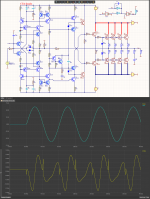
Another proof of your total technical illiteracy.
I showed you how it works without inductance and with a capacitive load.
But these are different loads and accordingly different frequency corrections are needed.
It takes a minimum of intelligence to understand this.
Well, you were not given one, unfortunately, but nothing can be done about it.
I showed you how it works without inductance and with a capacitive load.
But these are different loads and accordingly different frequency corrections are needed.
It takes a minimum of intelligence to understand this.
Well, you were not given one, unfortunately, but nothing can be done about it.
Our supreme audio amplifier designer's modus operandi has been to dodge challenging questions all along, then shifting position and sniping at us from a new angle and insinuating how deficient we are and as in earlier posts pointing towards where we are on the Dunning-Kruger curve, with that in mind I would take the liberty and "diagnose" our professor, here:
https://ru.wikipedia.org/wiki/Грандиозность
So I'm afraid it will be a hard task to convert our patient who seems to be behind a rigid psychological firewall.
https://ru.wikipedia.org/wiki/Грандиозность
So I'm afraid it will be a hard task to convert our patient who seems to be behind a rigid psychological firewall.
Astaro,write at what amplitude these values are obtained at the output. I see that the 8 ohm load and 20kHz frequency only. I don't use LTspice, so it may be indicated somewhere, but I didn't find it.
One last attempt to bring you down, Sandi, to the ground.
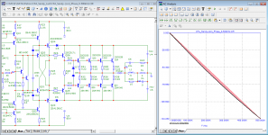
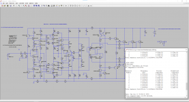
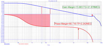
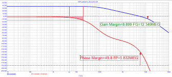
At one time, Otala came to the conclusion about the importance of the frequency of the first pole, preferably above the upper frequency of the sound range.
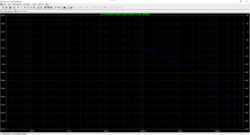
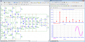
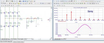
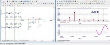
Here are the loop gain diagrams of two amplifiers with different first pole frequencies. In one amplifier, the loop gain at a frequency of 5 kHz is 5 times higher than in the second, and the level of distortion, instead of being 5 times lower, is more than 5 times higher, and the spectrum of harmonics is wider.
The measurements were taken on the 4th period. It's scary to imagine what the difference will be in the 2nd period...
At one time, Otala came to the conclusion about the importance of the frequency of the first pole, preferably above the upper frequency of the sound range.
Here are the loop gain diagrams of two amplifiers with different first pole frequencies. In one amplifier, the loop gain at a frequency of 5 kHz is 5 times higher than in the second, and the level of distortion, instead of being 5 times lower, is more than 5 times higher, and the spectrum of harmonics is wider.
The measurements were taken on the 4th period. It's scary to imagine what the difference will be in the 2nd period...
Attachments
-
 03_AMP-Lateral-inv_Buf_1W_20kHz-spectr.png38.2 KB · Views: 124
 -
 02_CFA_Sandy-(cor)_1W_5kHz-spectr.png36.3 KB · Views: 130
 -
 02_AMP-Lateral-inv_Buf_1W_5kHz-spectr.png38 KB · Views: 125
 -
 01_CFA_Sandy-(cor)_Loop-Gain.png13.8 KB · Views: 116
 -
 01_AMP_Lateral-inv_Buf_Loop-Gain.png13.7 KB · Views: 109
 -
 03_CFA_Sandy-(cor)_1W_20kHz-spectr.png35.7 KB · Views: 116
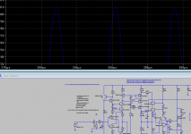
petr_2009, these pictures with distortions are your area of responsibility, because the models are different and no one can check what you did there, because you keep your model with you and do not post it on the forum. In order not to be unfounded, I apply measurements in my Sandy amplifier model with the same conditions: 4 ohms, 4V of amplitude, for 4 periods. As you can see, the results are different, the distortion is noticeably lower. Your results are not a reason to make claims to Sandy Todorov.
Attachments
petr_2009, these pictures with distortions are your area of responsibility, because the models are different and no one can check what you did there, because you keep your model with you and do not post it on the forum.
you are inattentive, the model is in the archive
https://www.diyaudio.com/community/...amental-improvement-sandy.346751/post-7139288
p.s.
post your model
Last edited:
One gets the impression that you read something but did not read it to the logical end. A high pole is certainly necessary for quality growth, but it includes limiting the spectrum at the input - this is in Polak's further work on amplifier correction.At one time, Otala came to the conclusion about the importance of the frequency of the first pole, preferably above the upper frequency of the sound range.
Judging by your simulation results, you have no idea with what value of gain before coverage and after coverage by the total negative feedback, the pole can take on a well-defined value in frequency.
Hence the various metamorphoses with the understanding of certain modeling results...
- Home
- Amplifiers
- Solid State
- Apex A40 fundamental improvement. (Sandy)