I have modified the driver responses to avoid the directivity issues during merging now by using the process that hifijim outlined above.
Please find the attached updated measurements with vituixcad project.
This configuration really looks like a hard one to design crossover for me.. 😀
Anyway I try to tweak, one of the graphs gets into a chewed up shape. either direcitivty, or the power response or the on-axis.
Latest iteration. This time the mid woofer on top of tweeter configuration..


I will try to study hifijim's crossover design next.
@tktran303: Thanks. I am finding this one a bit hard... I will try out your suggestion about LR2.
@Juhazi: Now I really feel like I should have gone with a better midrange..
Please find the attached updated measurements with vituixcad project.
This configuration really looks like a hard one to design crossover for me.. 😀
Anyway I try to tweak, one of the graphs gets into a chewed up shape. either direcitivty, or the power response or the on-axis.
Latest iteration. This time the mid woofer on top of tweeter configuration..
I will try to study hifijim's crossover design next.
@tktran303: Thanks. I am finding this one a bit hard... I will try out your suggestion about LR2.
@Juhazi: Now I really feel like I should have gone with a better midrange..
Attachments
As Juhazi suggested, it appears to me that the vertical response is the thing driving the 3-4khz hump. Your ER Total in this area exactly matches the ER Vertical hump. You can verify this by plotting all three ER traces and see which is driving ER Total behavior. Since your CTC is already set, you can manipulate the behavior with asymmetric slopes and crossover frequency. Aiming for standard slopes will not work here.
Also, I would start taking vertical measurements, instead of relying on VC's assumptions about vert vs hor. Sure it will be close, but when you move vertically, very small changes make a big impact on phase summation in the crossover region, so if VC's vertical calculation is off just a tiny bit from reality, I suspect it might have outsized impact on your modeled responses.
Also, I would start taking vertical measurements, instead of relying on VC's assumptions about vert vs hor. Sure it will be close, but when you move vertically, very small changes make a big impact on phase summation in the crossover region, so if VC's vertical calculation is off just a tiny bit from reality, I suspect it might have outsized impact on your modeled responses.

Thanks augerpro.. 🙂As Juhazi suggested, it appears to me that the vertical response is the thing driving the 3-4khz hump. Your ER Total in this area exactly matches the ER Vertical hump. You can verify this by plotting all three ER traces and see which is driving ER Total behavior. Since your CTC is already set, you can manipulate the behavior with asymmetric slopes and crossover frequency. Aiming for standard slopes will not work here.
Also, I would start taking vertical measurements, instead of relying on VC's assumptions about vert vs hor. Sure it will be close, but when you move vertically, very small changes make a big impact on phase summation in the crossover region, so if VC's vertical calculation is off just a tiny bit from reality, I suspect it might have outsized impact on your modeled responses.
I am planning to take vertical measurements. Probably over next weekend.
I tried to take it this time but the curved cabinet was making things difficult and had stability issues with measurement setup.. So I got frustrated and gave up.
I will try taking it next week somehow
Just one more for today


I really don't know what to do about that veritical dimension ditch in response around 2kHz though.. 😀
I really don't know what to do about that veritical dimension ditch in response around 2kHz though.. 😀
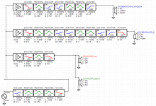
My first thought was to play with phase near 2 khz. I had best results by adding DSP delay in the amp symbols. I just used delay to make the main beam horizontal rather than tilted. Then I did a round of manual EQ to further flatten the response while keeping PIR and PwrResp relatively smooth. I used predicted preference rating to judge tradeoffs. My polar maps are normalized to separate color changes due to axial response from those due to directivity. The IR and step responses are not pretty.
Attachments
For me, the first step in setting up an active filter is to EQ the drivers to a reasonably flat smooth response. This then becomes the starting point for developing a crossover.
First the woofer raw response

And now with EQ, but no crossover


Nothing above 1000 Hz matters, so this driver looks reasonable... BSC is incorporated, and some modest EQ has flattened it to a reasonable degree.
First the woofer raw response
And now with EQ, but no crossover
Nothing above 1000 Hz matters, so this driver looks reasonable... BSC is incorporated, and some modest EQ has flattened it to a reasonable degree.
Next is the mid driver, SB15CAC
Raw response

Now with EQ, but no crossover

Given the pass band of this driver, the region from 100 Hz to 4kHz is the most important to focus on.


When doing a complicated EQ such as this mid driver requires, I find shelf filters very helpful, rather than a long series of PEQ's.
Raw response
Now with EQ, but no crossover
Given the pass band of this driver, the region from 100 Hz to 4kHz is the most important to focus on.
When doing a complicated EQ such as this mid driver requires, I find shelf filters very helpful, rather than a long series of PEQ's.
Now the Tweeter... Raw response first

Now with EQ but no crossover


I have never EQ'd a waveguide tweeter before. It seems to me that shelf filters are particularly useful here.
Now with EQ but no crossover
I have never EQ'd a waveguide tweeter before. It seems to me that shelf filters are particularly useful here.
If we just slap on a LR2 at 300 Hz and a BW3 at 2k, the results are not too bad. Actually it has some promise.


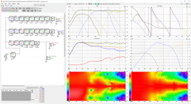
What I like about this filter is the predicted in room (PIR) response is quite good. The power response has a +1 dB bump from 3k - 4k, which leads to a -2 dB dip in DI. Overall this is very likely to be insiginificant.

What I do not like about this filter is the horizontal polar response. Starting at 30 degrees and going all the way through 90 degrees, there is a peak at 3.2k. It is most prominent at 40 to 60 degrees off axis.

What I like about this filter is the predicted in room (PIR) response is quite good. The power response has a +1 dB bump from 3k - 4k, which leads to a -2 dB dip in DI. Overall this is very likely to be insiginificant.
What I do not like about this filter is the horizontal polar response. Starting at 30 degrees and going all the way through 90 degrees, there is a peak at 3.2k. It is most prominent at 40 to 60 degrees off axis.
If we try 2nd order at 2k, the horizontal polars improve.


Horizontal polars are much improved. But other parameters have degraded. The vertical polar response now has much deeper nulls. The power response and DI are a bit less even. The PIR is slightly less optimal, and the ER has a rising response from 2k to 3k that Fluid warns us against.
Also please note that the 10-degree horizontal curve has some kind of measurement error in it, note the dramatic dip from 200 to 1k. This shows up in all the sims.

So, some continuing refinement is needed.
Horizontal polars are much improved. But other parameters have degraded. The vertical polar response now has much deeper nulls. The power response and DI are a bit less even. The PIR is slightly less optimal, and the ER has a rising response from 2k to 3k that Fluid warns us against.
Also please note that the 10-degree horizontal curve has some kind of measurement error in it, note the dramatic dip from 200 to 1k. This shows up in all the sims.
So, some continuing refinement is needed.
What I do not like about this filter is the horizontal polar response. Starting at 30 degrees and going all the way through 90 degrees, there is a peak at 3.2k. It is most prominent at 40 to 60 degrees off axis.
View attachment 1098208
I’m in agreement Jim,
Its hard to know exactly which will be preferable. I feel It depends on the room and listening position(s).
In terms of horizontal responses, Between a flat 2-4 KHz in the on-axis and a peak in 2-4 KHz off axis, VS a dip in the on-axis, but resultant smooth and flat power response and predicted in room response (see attached as an example); I think I’ll prefer take the latter.
But latter is perhaps more Advantageous in smaller rooms or when the speaker is on the narrower width of the room; where side reflections at 45-90 degrees will be significant.
The former may be advantageous when listening in large rooms or in the close distances to the speaker eg. 1m, where direct sound dominates the reflected sound.
Again, I don’t have good evidence for this.
But with DSP it’s easy to listen for oneself in one’s own room. The other thing I do in crossover tuning is to use VituixCAD2 with a 20dB vertical scale (let us all recall that is the difference between 1 Watt and 100W) and 50dB as defined by CTA2304A is close the difference between nice and loud and close to imperceptible (depending on noise floor of the room)
Reference-
https://www.audiocheck.net/audiotests_dynamiccheck.php
Vineeth do you have ability to switch between crossover settings instantaneously and listen to Jim’s various XOs?
Last edited:
Actually, I am hoping that Vineeth can make vertical polar responses of mid and tweeter before he starts implementing anything. Fine tuning a sim to the level we are striving for requires the best available data. I found that if I used only horizontal measurements, my power and DI sims were +/- 2 dB acurate, and if that is all we can expect from the sim, then basically we are done with simulation. If we want better than that, vertical measurements are needed.
I also recommend an outdoor ground plane measurement of the woofer box, on-axis is all that is needed. I think we really need to confirm the shape of the woofer response up to about 800 Hz. I could be wrong, but the woofer response still looks odd to me.
I also hope that someone else jumps in with a fresh perspective on the DSP filter. Vineeth has asked for ideas, and I am very interested in how other folks design a DSP filter.
j.
The bulk of the 3K problem seems to be in the tweeter, the EQ looks to have made it slightly worse and the SB15 bounces back around those same frequencies so it's off axis contribution is also higher than desirable there. I don't know if it is an optical illusion but Vineeth's waveguide looks slightly smaller than mainframe's.Now the Tweeter... Raw response first
Now with EQ but no crossover
Usually a small value Capacitor or a high pass filter with an Fc near 18 to 20K works to undo the mass and inductive rolloff.I have never EQ'd a waveguide tweeter before. It seems to me that shelf filters are particularly useful here.
Yeah the horizontal of the tweeter has a 3-4khz bump off axis also. So that plus the vertical ER are unfortunately pushing up response there. Must be baffle diffraction intruding, I don't see it with the waveguide measured on my test baffle. The 6" version I used with the speaker sent to Erin doesn't do that at 3-4khz, although it does a bit at 2khz where it is already rolling off so not an issue. Vineeth is this the 4"? What does the diffraction model look like?
First of all, Thanks a lot @hifijim, @nc535, @fluid, @tktran303 and @augerpro. Thank you all for helping out this much.
I am making mistakes but definetely learn a lot more than I expected from this one.. 😀 This is really good.. 🙂
@hifijim: I will definetely try to take the vertical polars of the two way top module over next weekend or so.. I will also try to check the woofer response.
@tktran303 : Yes I can change between all these different crossovers on my PC and listen. Till i do next round of measurements, I am definitely going to program all these crossovers into PC and listen to them.. 🙂
@fluid and @augerpro : This is the smallest waveguide of them all. The 4inch one. Hence it is smaller than the 5inch one which mainframe99 has used in his build. I got these waveguides made almost at the beginning of this project. The only thing I knew about waveguides at that time was Kimmosto's post about using smaller waveguides, probably ones that are not as big as the woofer diameter. He might have mentioned other conditions also along with it like under what conditions such a decision should be taken, which I might have missed.. 😀
@augerpro: can you please let me know how we can get the diffraction model for the waveguide on the baffle?
I have done vituixcad diffraction models for regular tweeters/woofers on baffle but not for one on a waveguide.
I don't know if this is diffraction (caused by me not terminating the waveguide properly with rounding/chamfer not immediately starting right at the edge of the waveguide), But there is something that causes a bunching of curves from 0 to 30 degrees off axis around 3-4 kHz. Maybe this is causing some issue?
In terms of horizontal responses, Between a flat 2-4 KHz in the on-axis and a peak in 2-4 KHz off axis, VS a dip in the on-axis, but resultant smooth and flat power response and predicted in room response (see attached as an example); I think I’ll prefer take the latter.
Of course it is possible to globally EQ the response such that any one curve is nearly ideal. If we highly value one particular curve, such as PIR, we can force it to be flat. To me it seems counter-intuitive, so I have never had the nerve to try it.
If we did, we might end up with something like this
Would this work? I suppose it would. I would love to hear from someone with first-hand experience in optimizing PIR at the expense of on-axis and listening window response.
Attachments
We all make mistakes. It is a mark of good character to be willing to make them and acknowledge them in public. You have a great project !I am making mistakes but definetely learn a lot more than I expected from this one..
This what I suspected but it is good to have it confirmed
This is the tricky part about separating out advice, it may not turn out be universally true by itself. The 4 inch waveguide is not significantly less directive at the crossover point than the woofer is, which is really what the advice was aimed at, even though it is physically smaller, the SB driver is quite wide at the crossover point relatively speaking.I got these waveguides made almost at the beginning of this project. The only thing I knew about waveguides at that time was Kimmosto's post about using smaller waveguides, probably ones that are not as big as the woofer diameter. He might have mentioned other conditions also along with it like under what conditions such a decision should be taken, which I might have missed.. 😀
Slightly further on in the thread he says
"Wave guide is quite large - possibly too large in many modern speakers though large wave guide might be needed with shoe box enclosure"
In this case a DI bump below the crossover from the matched directivity of the horizontal sizes is probably the better trade.
I suspect the extra little bit of extra flat baffle combined with the overall width is probably where that off axis rise is coming from.I don't know if this is diffraction (caused by me not terminating the waveguide properly with rounding/chamfer not immediately starting right at the edge of the waveguide), But there is something that causes a bunching of curves from 0 to 30 degrees off axis around 3-4 kHz. Maybe this is causing some issue?
I think the graph above of the on axis and listening window shows why forcing any curve to a specific target doesn't work in all cases. If the speaker is very smooth and consistent in directivity then it might work better. One of the ASR posters who has a speaker database runs an EQ algorithm that targets the SM PIR as it generally increases the Olive score. I haven't seen many where I think the after EQ is anything other than different. I have spent a long time changing the tonal balance from in room measurements of my line arrays. The best result has never been a straight line. Not far off it visually, but the difference in sound was much more than the graph would suggest.Would this work? I suppose it would. I would love to hear from someone with first-hand experience in optimizing PIR at the expense of on-axis and listening window response.
You can use a regular driver source for the diffraction model to get an idea how it will look even without the waveguide. Then compare that to my test baffle waveguide response just to be sure any widening/narrowing of the baffle diffraction doesn't happen to align with a similar widening/narrowing of the native waveguide response. My prototype speaker has a 1.25" roundover starting not more than .125" from the waveguide. Yours has a bit of flat space between waveguide and edge, and that compromises things (a bit) when you model it in ABEC. I think what happened here is just a very unlucky series of issues all falling on the same frequency range in the same way. For example, the horizontal of the un-EQed tweeter in your plot doesn't have a hump at 3-4khz until you EQ down the hump at 2khz. Then the vertical early reflections just happen to also create a huge hump 3-4khz simply due to the selection of ctc and crossover. The 4" really isn't ideal for a sub-3khz crossover to a 15cm woofer. Directivities don't quite match. Add on top of that the little waveguide is still going to "illuminate" the baffle edges, so diffraction modeling is still important. Like I said, just a very unlucky series of issues all stacking up in the same way.@augerpro: can you please let me know how we can get the diffraction model for the waveguide on the baffle?
I have done vituixcad diffraction models for regular tweeters/woofers on baffle but not for one on a waveguide.
I don't know if this is diffraction (caused by me not terminating the waveguide properly with rounding/chamfer not immediately starting right at the edge of the waveguide), But there is something that causes a bunching of curves from 0 to 30 degrees off axis around 3-4 kHz. Maybe this is causing some issue?
I don't know how high the SB15 can run, might need a passive notch on the breakup to run it up high, but it might be worth raising the crossover to near 3khz and see if that improves things.
- Home
- Loudspeakers
- Multi-Way
- A 3 way design study