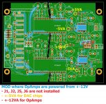
Yes, J1, J2, J5 and J6 are not installed and VA slots are for V12.Judging by schematic, J5 and J6 jumper not jumped with a connection to 5V, and VA slots are for V12 then? Always like to double check 😁
+-5VA supply for DAC chip is then one free pin from not installed jumpers (carefully trace these pins) ...
... double check the image 🤣
Attachments

First try to replace the opamps 🙂Hi, guys. I have a some trouble with 1862 DAC. He's start to wheezing but at first there was a squeak. I was tried to change opamps on 797 (I have a pair) - I was heard a liitle squeak on min volume. I have a sound and there is no problem - I still can listen to music.
This incident has started after non working amp (Audio Analogue) which they brought to me and didn't tell me about that. He has a strong wheeze and there is no sound. I turned off right away and never turned it on again. That's what happened with my DAC.
What might have happened? I also speak with some people about my problem and they recommended to change opamps on 604 and also check the details after chips.
Thank you for the confirmation 🤗 Soon another pcm63 dac is joining the club 💪🏻Yes, J1, J2, J5 and J6 are not installed and VA slots are for V12.
+-5VA supply for DAC chip is then one free pin from not installed jumpers (carefully trace these pins) ...
... double check the image 🤣
Don't worry, I know all about it, as for THD I meant on tubes because the ECC88 has less distortion than the 6HM5 for the same output voltage.Be careful here. Paralleling DACs does not increase the signal voltage amplitude, while maintaining the level of distortion. Since the passive I/V distortion is a function of the signal voltage amplitude developed at the current output pin of the DAC chip, increasing the voltage amplitude at that pin increases DAC distortion. To make effective use of paralleled DACs with a passive I/V requires reducing the value of the I/V resistor by the same factor as the number of paralleled DACs. Parallel two DACs, then divide the I/V resistor by a factor of 2. Four DACs, then by a factor of 4.
The result is no increase in signal voltage amplitude at a given level of distortion. The I/V stage's output impedance, however, goes down by the same factor as how many DACs you have paralleled. Aside from the reduction of random noise, and a certain type of resistor based DAC chip quantizer non-linearity, and which, by far, are the primary benefit from paralleling DAC chips. Paralleling DAC chips does potentially enable the I/V stage to directly drive the output line connecting the DAC box to the next box in the signal chain (preamplifier or power amplifier), without an additional output amplification stage. Assuming , of course, that the limited signal voltage available from a resistor I/V is of sufficient amplitude. Which in most instances, I suspect that it won't be.
However, I brought the signal to the cathode instead of the grid, so the input resistance is even lower than Rk, which is on the 6MH5 and with 3*PCM.. only 16R, for 4*PCM.. I will go to 10R. It means that Zin will be even lower than 10R for four PCM1702.
For 6HM5 I still have to calculate Zin with Rk of 10R, for example 6S4P with Rk=50R has Zin~30R.
I haven't tried the ECC88 yet with a grounded grid because of the low gain, but with 4*PCM... and Rk around 25R, it would have a large output voltage to drive (normally with a buffer) the amplifier .
Thank you for your concern.
Attachments
Do you think that's was opamps?First try to replace the opamps 🙂

I had misinterpreted your post as suggesting that you were planning to parallel DACs in order to achieve the higher output swing. My error.Don't worry, I know all about it, as for THD I meant on tubes because the ECC88 has less distortion than the 6HM5 for the same output voltage.
However, I brought the signal to the cathode instead of the grid, so the input resistance is even lower than Rk, which is on the 6MH5 and with 3*PCM.. only 16R, for 4*PCM.. I will go to 10R. It means that Zin will be even lower than 10R for four PCM1702.
For 6HM5 I still have to calculate Zin with Rk of 10R, for example 6S4P with Rk=50R has Zin~30R.
I haven't tried the ECC88 yet with a grounded grid because of the low gain, but with 4*PCM... and Rk around 25R, it would have a large output voltage to drive (normally with a buffer) the amplifier .
Thank you for your concern.
I have a Miro AD1860 and building the AD1862. I am hoping to use an old iPhone 7 running Tidal as the source.
Does anyone have a {iPhone lightning -> USB -> I2s} setup that works with these DACs?
I have tried several lightning to USB cables -> PMC2706 without success.
Does anyone have a {iPhone lightning -> USB -> I2s} setup that works with these DACs?
I have tried several lightning to USB cables -> PMC2706 without success.
Lightning to I2S (or lightning to usb to I2S) is mystery for me.
Try to use some Bluetooth to I2S device (you can cheaply buy a ready made one) 😉 ... hope the iPhone 7 has good bluetooth audio streaming 🤔
https://www.aliexpress.com/item/4000334914773.html (CSR8675) ... it was cheaper in the past, but the price increased 🤔
or this https://www.aliexpress.com/item/1005004563579498.html (QCC3031 is newer chip)
... or maybe QCC3005, QCC5125, ...
Last edited:
Yes, it does work if you get the specific accessory. I got the usb adapter cable for iPad and connected usb input of dac to this.... It is detected in iPad.... I have used gen1 usb to i2s from jlsounds.I have a Miro AD1860 and building the AD1862. I am hoping to use an old iPhone 7 running Tidal as the source.
Does anyone have a {iPhone lightning -> USB -> I2s} setup that works with these DACs?
I have tried several lightning to USB cables -> PMC2706 without success.
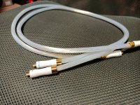
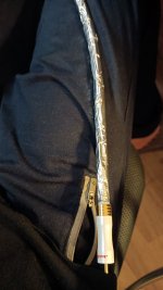
Hi, Miro! I solved my problem with Dac. It was all the cable's fault - he is without screen. After I changed him on my Viablue - I was heard only music and silent. I use the same opamps (LM6171). So I took the cable (he from ali) and wrapped it with aluminium foil and tried again - it was success - no noises.
I was already ordered OPA604 but still waiting.
I still haven't found a good box for it)
I was already ordered OPA604 but still waiting.
I still haven't found a good box for it)
Attachments
Maybe from old satellite receiver or some tape recorder.....empty heavy boxes are not rare those days, just need a little painting!... In concrete as well ! Migth be too big though... and listen to music with no friends anymore is a little bit borring !
I told that my DACs are literally for all, no degree in science is required 🤣Tbh i'm still amazed that your dac still works after such a soldering job 😅 Glad you have found the issue 👍

Exactly, buy or get something like that cheaply in a good visual condition, nice looking device, and change the insides 😉Maybe from old satellite receiver or some tape recorder.

Iggy, you supply the bev and I’ll be over with Breakout for an all nighter! 🤣 🕹👾🎮
Hi Miro. I’ve got my PCM63 boards stuffed and just waiting on chips to arrive. I wanted to clarify MSB adjustment: I will not be making provisions for MSB adjustment. Any new thinking on whether C39-42 should be stuffed in this case?PCM63P
Ok guys, here it is 😎
…
PCB contains pins for optional MSB adjustment circuitry, in that case C39 - C42 will not be installed, or can be?
- Home
- Source & Line
- Digital Line Level
- DAC AD1862: Almost THT, I2S input, NOS, R-2R