Some op ams like njm4558,4559 are known to do well when overloaded.Tons of guitar effects based on njm4558...
Njm4559 is slightly better as slew rate and offset and it was preffered in many semiprofessional audio equipment.
M5218,19,20 were better equiped to handle short increased ouput bursts as well as higher voltage output capability.Now while ne5534 can withstand higher supply voltages I don't think anyone studied its harmonics when hit hard and supplied at +-15V.
There's a bit of theory around an op amp going into hard clipping but not all op amps behave the same.I stated my prefferences as to why biasing the input should be prefferably done through a high value resistor ...Other opinions might be valid depending on op amp choice.If the riaa network impedance is right higher supply voltages than +-15v should be preffered and most op amp based phono preamps that I studied go with at least +-17.5v supply.
Last edited:

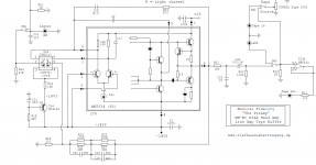
Something like the attached from Musical Fidelity? Also have a look at TI app-note 222 page 7 that has a similar solution for the LM318.If you make a pcb for 2 x ne5534 make space for 6 additional low noise transistors (ksc1845) and 4 antiparallel clamping diodes for the future.Look back and see there's a schematic where the input trz inside ne5534 were replaced by output transistors.
https://www.diyaudio.com/community/...s-in-high-frequency-range.390030/post-7129131
Note different pinout (pin 5 & 8 swap) between NE5534 and LM318. Some may prefer the LM318 solution as it is running at 1/5 the current in the input pair compared to the NE5534. Additional advantage of lower bias-current when direct coupled to MM cartridge. The circuit in AN222 could probably benefit from having R4 replaced by a CCS like in the Vogl3 schematic in post 44 by Dreamth above.
Then again, others would recommend JFET over the LM394 for MM cartridge
Attachments
The tail current of the differential pair in the LM318/LM394 circuit is close to the noise optimum for a typical moving-magnet cartridge. (See https://www.diyaudio.com/community/...ono-stage-85-dba-sn-ratio.387375/post-7135693 , ignore the values for 20 kHz spot noise and multiply by 1.4 * sqrt(2) * 2 * (1 + 1/hFE) ~= 4 to get the optimal tail current for a symmetrical differential pair with 500 mH cartridge. The result is about 100 uA to 150 uA.)
The NE5534/SSM2210 circuit makes sense for moving coil cartridges or as a compromise for a circuit that has to work with moving coil as well as moving magnet. When you only use it for moving magnet, you pay extra money to get more noise, as the tail current is well above the optimum (÷).
(÷): It may seem better in Stereophile, though, as the story goes that they always measure with a 600 ohm resistive source, never with a realistic cartridge inductance. I could be misinformed, I never read Stereophile.
Last edited:
First circuit has about 900uA/2 the second has 190uA/2. I have no ideea why the first circuit is as it is, but most people I read in the past placed the optimum collector current around 1mA to overcome the shot noise in known low noise bipolar types.I saw a distribution of collector currents between 10uA and 1mA in real circuits, but it might very well be that the optimum current depends on the particular chosen transistor too...If that's so then we have to fake it until we make it...
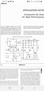
There's also the frequency response of bipolar trz vs jfet trz at a given current underlined in the Siliconix appnote and Nick and you made very clear that you like jfets so I'll give back a bit 🙂
I told for too many times why I preffer bipolar trz in ordinary phono preamps
even though I have one favorite phono preamp with jfet inputs and I won't repeat that again.I tried to replicate kenwood l-02A preamp, but there's one transistor I can't find...and replacing it is tough bussiness.
Attachments

Marcel,The tail current of the differential pair in the LM318/LM394 circuit is close to the noise optimum for a typical moving-magnet cartridge. (See https://www.diyaudio.com/community/...ono-stage-85-dba-sn-ratio.387375/post-7135693 , ignore the values for 20 kHz spot noise and multiply by 1.4 * sqrt(2) * 2 * (1 + 1/hFE) ~= 4 to get the optimal tail current for a symmetrical differential pair with 500 mH cartridge. The result is about 100 uA to 150 uA.)
The NE5534/SSM2210 circuit makes sense for moving coil cartridges or as a compromise for a circuit that has to work with moving coil as well as moving magnet. When you only use it for moving magnet, you pay extra money to get more noise, as the tail current is well above the optimum (÷).
(÷): It may seem better in Stereophile, though, as the story goes that they always measure with a 600 ohm resistive source, never with a realistic cartridge inductance. I could be misinformed, I never read Stereophile.
as far as I recall, John Atkinson, the former editor and the guy that did all the measurements (and still does) at Stereophile, shorts the input to the phono amp and then measures the noise. He actually came on this site a few yrs ago and it was suggested that to accurately gauge the noise performance he should use a real cartridge source. Of course if you suddenly start using a real source impedance and the noise figures go up on subsequent reviews, it would be unfair to those later phono amps that you test, so I think that's why he demurred.
It is not possible to get 85dB wrt 3 or 5mV with a real-world cartridge with a standard 47k as you know. The thermal noise of the cart in // with the load generates about 3uV noise. Stuart Yaniger who used to frequent the forum and has now left, made a very nice spread sheet to calculate the noise by inputting your cartridge characteristics. His spread sheet was based on a National Semiconductor applications note dating back to the early 1970's. I modified his spread sheet to allow different opamps or discrete devices to be compared. You can download the spread sheet here:-
https://hifisonix.com/so-just-how-quiet-is-your-phono-stage/
(Separately, I've suggested elsewhere that there should be a 'standard cartridge' that we use to compare MM noise - 500mH in series with 1.35k Ohms)
The tail current of the differential pair in the LM318/LM394 circuit is close to the noise optimum for a typical moving-magnet cartridge. (See https://www.diyaudio.com/community/...ono-stage-85-dba-sn-ratio.387375/post-7135693 , ignore the values for 20 kHz spot noise and multiply by 1.4 * sqrt(2) * 2 * (1 + 1/hFE) ~= 4 to get the optimal tail current for a symmetrical differential pair with 500 mH cartridge. The result is about 100 uA to 150 uA.)
I believe the popular Ortofon Red/Blue/Black series of pickups is actually even more at 700uH.
https://www.ortofon.com/ortofon-2m-red-p-317
I have not seen published induction data for High Output MC type pickups, but suspect that they have lower L and hence the circuit would be closer to optimal with this type of pickup. In general there seem to be little discussions optimizing to HO-MC types and noise here at DIYaudio. Is this because they have similar L-values as MM type?
Of course if you suddenly start using a real source impedance and the noise figures go up on subsequent reviews, it would be unfair to those later phono amps that you test, so I think that's why he demurred.
That's easily solved: measure with a realistic source impedance and with a short, report both numbers and explain that the first number is realistic and the second only given for backwards compatibility.
Measuring with a shorted input is unfair to designers who understand noise optimization, as it makes their designs look inferior to those designed by people who haven't a clue and use bipolar input stages biased at way too high currents.
I have my own method: optimize for the cartridge impedance at 3850 Hz for RIAA- and A-weighting, 5179 Hz for RIAA- and ITU-R 468-weighting.Stuart Yaniger who used to frequent the forum and has now left, made a very nice spread sheet to calculate the noise by inputting your cartridge characteristics. His spread sheet was based on a National Semiconductor applications note dating back to the early 1970's. I modified his spread sheet to allow different opamps or discrete devices to be compared. You can download the spread sheet here:-
https://hifisonix.com/so-just-how-quiet-is-your-phono-stage/
(Separately, I've suggested elsewhere that there should be a 'standard cartridge' that we use to compare MM noise - 500mH in series with 1.35k Ohms)
https://worldradiohistory.com/UK/Wireless-World/00s/Electronics-World-2003-10-S-OCR.pdf pages 38...43. One section of the switch in Fig. 5 has been drawn in the wrong state and I mixed up the terms spectral density and power spectral density.
Last edited:
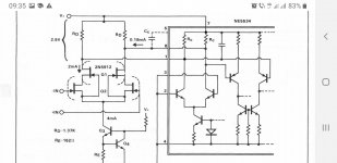
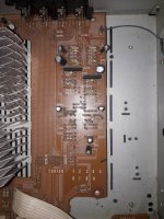
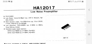
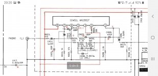
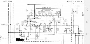
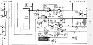
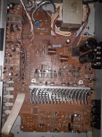
They didn't get into making high speed trains for being clumsy.. this is how they gave the ability to work with mm carts to a 500mW op amp in 1980.Also see the elegance of pcb design:
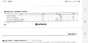
Hitachi ha-2700, 3700...HA12017:
Hitachi ha-2700, 3700...HA12017:
Attachments
-
 20221027_195633.jpg610.3 KB · Views: 101
 -
 Screenshot_20221027-200137_Word.jpg91.6 KB · Views: 102
 -
 Screenshot_20221027-200013_Word.jpg96 KB · Views: 109
 -
 Screenshot_20221027-202052_Word.jpg125.3 KB · Views: 111
 -
 Screenshot_20221027-201052_Word.jpg160.2 KB · Views: 113
 -
 Screenshot_20221027-202457_Word.jpg177 KB · Views: 114
 -
 20221027_203144.jpg532.5 KB · Views: 99
 -
 20221027_201405.jpg737 KB · Views: 104
Hello all,
It has been a while that Im searching about the DC voltage offset on an op amp out put and its effects on AC voltage which we care about. I have noticed in some designs that DC offset varies from 35 to few mili Volts on the op amp output. So what would be the effect on AC voltage (if it has any at all)? What are the limits?
I appreciate your consideration,
Cheers,
Alan.
None, in principle, if it is blocked somewhere downstream (unless it is so close to the supply voltage that there is no headroom left for the signal).
You also don't want to hear an enormous bang when you switch to a different source, so the offset at the source selection switch input has to be much smaller than the signal.
- Home
- Source & Line
- Analogue Source
- Advise needed on a phono preamp (occasional harshness in high frequency range)