Nice pathfinding work AddiDub!
I wonder if the Modushop 5U 500 could handle this passively? But as ZM suggested, better get some air blowing on those fins asap!

I wonder if the Modushop 5U 500 could handle this passively? But as ZM suggested, better get some air blowing on those fins asap!
I can't set up an amp deeper then 400mm. I wonder if it makes sense to use mono block chassis with two heat sinks each? Like the new 4U 400 mono blocks from modushop? That would cost me another 750 Euros (can't afford this right now), including UMS holes, taxes and shipping 😱😱I wonder if the Modushop 5U 500 could handle this passively?
But is it possible to move 4 of the 8 transistors to the other heat sink without using expansion boards? I don't think so..
Attachments
I agree with you that the point of this exercise is to use one board per channel with all mosfets attached so you do not have to span to the other side via flying leads.
Do you have any fans on hand to assist with cooling? Or is the chassis just so hot you need a wind tunnel to maintain a reasonable temperature.
Do you have any fans on hand to assist with cooling? Or is the chassis just so hot you need a wind tunnel to maintain a reasonable temperature.

The aim was to build an Aleph 35+ to see where we can go with only one main board and no expansion cards. To achieve more power compared to Aleph 30 the rail voltage and quiescent current had to go up.Do you really need to run it so hot at 2.7A? Is it for the power on 4 Ohm or the THD figure? Or?
By the way, here are my scope pics of one of my channels:
Clipped waveforms @ 18V RMS into 8 ohm:
I am asking because I have a similar Aleph 40ish plan (already have PCBs and FETs) in a dissipante 5U/400. However, the bottleneck remains the heatsinks dimension. I made some simulations assuming 125 W dissipations and indeed the bias and/or rail voltage must be lower than yours.
At this point I am wondering if I should go with a plain A30 (6 FETs) or is it worth going for a kind of A30+ (with 8 FETs)? Citing Papa (here) "paralleling
devices at somewhat lower bias can give you greater transconductance" but I do don't know what this would mean sonically.
I cannot go with a 5U/500 and even with monoblocks (that deviate from the idea of an Aleph 40 IMO).
... I made some simulations assuming 125 W dissipations and indeed the bias and/or rail voltage must be lower than yours.
I think 125 W will still run hot on the 5U 400 enclosure, depending on your living room temperature. But not as hot as 150W for sure.
With your dissipation budget you could decide to optimise the amp for either 8-ohmish speakers or 4-ohmish speakers.
To achieve more power into "easy to drive" 8-ohmish loads, you could choose a rail voltage of 29V with bias set at 2.2A. This way you could achieve ~42W into a 8-ohm resistive load.
To achieve more power into "heavy" 4-ohmish loads you could go with 25V rails and 2.5A - that should give you ~50W into 4ohm resistive load.
For a dissipation budget of 125W per channel a 6-Mosfet configuration is still sufficient in my eyes. Each MOSFET will dissipate ~21Watts, which is okay (with a sufficient heatsink).
Last edited:
To achieve more power into "easy to drive" 8-ohmish loads, you could choose a rail voltage of 29V with bias set at 2.2A. This way you could achieve ~42W into a 8-ohm resistive load.
This will probably be my goal (at least to properly use the name Aleph 40 🙂). To be decided 6 or 8 FETs.
Can someone help me to interpret the "clipping" sinewave in post #605 above?
To me it doesn't look like normal voltage rail clipping, but I am not educated enough to interpret the waveform correctly.
Could it also be the current limiter circuit kicking in (bottom side of waveform)?
What kind of "ringing" does the waveform show in the top half of the picture?
To me it doesn't look like normal voltage rail clipping, but I am not educated enough to interpret the waveform correctly.
Could it also be the current limiter circuit kicking in (bottom side of waveform)?
What kind of "ringing" does the waveform show in the top half of the picture?
Could it also be the current limiter circuit kicking in (bottom side of waveform)?
lift one side of the resistor, feeding the voltage drop to the limiting transistor (that shorts the voltage drive to MOSFET(s)), and try again...?
pls share the circuit diagram..?What kind of "ringing" does the waveform show in the top half of the picture?
It's build according to the Aleph 30 Classic build notes (see first post of this thread), expect source and output resistors are 0.68 ohms instead of 0.47 ohms.pls share the circuit diagram..?
The upper ringing could be from the Aleph current source.
https://www.diyaudio.com/community/threads/aleph-clipping-mod.115674/
https://www.diyaudio.com/community/threads/aleph-clipping-mod.115674/
Thank you Dennis, for this hint. I checked the link, unfortunately all pictures are dead linked in this thread. But I found a PDF document about this matter:The upper ringing could be from the Aleph current source.
https://www.diyaudio.com/community/threads/aleph-clipping-mod.115674/
https://www.diyaudio.com/community/attachments/aleph-ccs-modification-pdf.479739
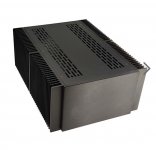
I'm looking for input and clever ideas on what chassis would work for a monoblock Aleph 1.2 build.
Modushop 5Ux500 stacked 2 high - per channel? I would need custom faceplates and backplates. I think this quantity of heatsinks would be up to the task. I made F5 Turbo V3's for a buddy a few years ago in 5Ux500. My thought process is that is 2x the POWER of the Turbos, so 2x the heatsinks should do the trick.
I checked with Modushop, and Gianluca can't do >5U height for the front and back plates. So I'd have to look elsewhere. Does anyone else know where I could get good-looking custom plates that are custom cut, drilled/tapped, and anodized? Or is there another turnkey chassis that could get the job done without all the custom work? Something from eBay or elsewhere?
Hi Randy,I'm looking for input and clever ideas on what chassis would work for a monoblock Aleph 1.2 build.
Modushop 5Ux500 stacked 2 high - per channel? I would need custom faceplates and backplates. I think this quantity of heatsinks would be up to the task. I made F5 Turbo V3's for a buddy a few years ago in 5Ux500. My thought process is that is 2x the POWER of the Turbos, so 2x the heatsinks should do the trick.
I checked with Modushop, and Gianluca can't do >5U height for the front and back plates. So I'd have to look elsewhere. Does anyone else know where I could get good-looking custom plates that are custom cut, drilled/tapped, and anodized? Or is there another turnkey chassis that could get the job done without all the custom work? Something from eBay or elsewhere?
I order my covers and front/rear plates from Schaffer AG here in Europe, but in the US there is the company Front Panel Express, practically the same as Schaffer. Take a a look at my Iron Pumpkin, all the panels are from Schaffer (https://www.diyaudio.com/community/...mals-tips-n-tricks-thread.336114/post-7017182). On the homepage you can download the designer software in order to make your own designs. It works great and easy: https://www.frontpanelexpress.com/
Glad you found that since in a rush I had attached the wrong link. 🙂 Anyway, I hope this helps.Thank you Dennis, for this hint. I checked the link, unfortunately all pictures are dead linked in this thread. But I found a PDF document about this matter:
https://www.diyaudio.com/community/attachments/aleph-ccs-modification-pdf.479739
I have a build question. I had low level hum in my Aleph 30 I couldn't solve, and repurposed the chassis for another amp. Today I realized that I'd been mounting the metallic backs of the bridge rectifiers directly to the metal chassis, meaning they were in ohmic contact with chassis ground and hence with each other. Now I can't read any DC resistance between those metallic backs and any of the four rectifier poles, however I can read a capacitance of 100-300pF between the metallic back and any of the four poles, depending on the pole. Could this be a source of hum? Do people insulate these metallic backs from chassis ground when the mount them?
Attachments

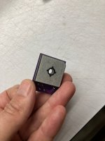
I mount my bridge rectifiers directly to the chassis of all my amplifiers and no hum at all out of my 103dB speakers.
- Home
- Amplifiers
- Pass Labs
- Classic Aleph Amplifier for Modern UMS Chassis Builder's Thread