Hello jdrouin - good to have you back in the thread! The thread has mushroomed because there are a number of DIYers who prefer the 2a3 to the ubiquitous 300b, which has been covered in a large number of threads. So the 2a3 fans have been coming out of the woodwork. We've had a lot of good contributions here and you have started a really interesting thread!
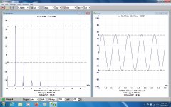
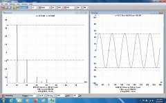
Another SE 2A3 Driver, on the bench today. The pentode section of a 6U8 provides the gain while the
triode section acts as an impedance convertor to drive the 2A3 input & Miller C of ~100 pF.
No problem at 50 KHz, well above the normal audio range. THD less than 1% even at 100V P-P,
more than enough to drive a 2A3 into clipping. Input to clip is ~0.8vrms.👍
The THD measurements were done using a PicoScope 3224.
Attachments


That's a really nice harmonic profile. That 0.1 uF screen cap is begging for an 0A3 bypass.Another SE 2A3 Driver
Thanks for posting it, John. Your data clarify how much driver DC current is needed for slew rate into 2A3 grid not to limit undistorted full power at highest frequencies. 50 kHz full blast at 5 mA driver's quiescent current! So, 20-30 mA drivers that some advocate are not necessary, and 2A3 seems to be not such a "difficult to drive" tube.Another SE 2A3 Driver, on the bench today. The pentode section of a 6U8 provides the gain while the
triode section acts as an impedance convertor to drive the 2A3 input & Miller C of ~100 pF.
No problem at 50 KHz, well above the normal audio range. THD less than 1% even at 100V P-P,
more than enough to drive a 2A3 into clipping. Input to clip is ~0.8vrms.👍
The THD measurements were done using a PicoScope 3224.
C'mon, this is classical pentode voltage amplifier, not power stage. Screen current is a couple of hundred uA. Using 30 mA gas regulator here would be like using artillery to kill flies.That's a really nice harmonic profile. That 0.1 uF screen cap is begging for an 0A3 bypass.
GNF to the pent cathode would result in a few dB only, for 2Vrms input sensitivity.THD less than 1% even at 100V P-P, more than enough to drive a 2A3 into clipping. Input to clip is ~0.8vrms.👍
Can we raise that number to say 12dB without too much stress on the stage distortion?
I guess the pent load changes as well with global feedback involved now... See http://www.r-type.org/vox/vox-013.htm
Last edited:
You make that sound like a bad thing. For me it's an easy route to a much lower and consistent screen supply impedance down to DC. Min operating current is 5 ma so not too dear.using artillery to kill flies
For fine tuning pent distortion the screen voltage is paramount.. so a regulated supply makes sense to me as well, as we are not after a low cost build after all.
Member
Joined 2009
Paid Member
Yes, a clean screen supply is desirable but something less drastic than a regulator tube would show a more prudent engineering approach. But if it gives a reason to add more tubes, how can that be argued with?! 👍
Exactly. The recommended screen supply is resistive voltage divider (which almost every designer ignores in favor of single resistor). Regulation can be improved by lowering resistors' values.Yes, a clean screen supply is desirable but something less drastic than a regulator tube would show a more prudent engineering approach. But if it gives a reason to add more tubes, how can that be argued with?! 👍
The answer is cannot. In pentode voltage amplifiers, gain and frequency response are in conflict. In John's schematic, the low gain (45) due to relatively low plate load (100 K) allows good HF performance. Gain can be increased by increasing plate load to 220 K or even 470 K, but HF roll off will be at 10 and 5 kHz, respectively.GNF to the pent cathode would result in a few dB only, for 2Vrms input sensitivity.
Can we raise that number to say 12dB without too much stress on the stage distortion?
I guess the pent load changes as well with global feedback involved now... See http://www.r-type.org/vox/vox-013.htm
OK, time for a test. Many ideas but sofar unsupported. So time for everyone to put some math to their claim.That's a really nice harmonic profile. That 0.1 uF screen cap is begging for an 0A3 bypass.
Or simply looks impressive, sounds better & so on. Lets hear what everyone thinks. Be sure to give an example
or how & where you heard of the modification. There will be no failures, just some fun. 😀

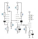
In John's setup the 6U8 triode Miller capacitance determines the stage bandwith and thus the
allowed gain. Why not replace it with a second pentode to lower input capacitance so the gain
could be maximized.
I can't emulate circuit behavior and excuse my limited 'paint' skills but I thought something
like this.
allowed gain. Why not replace it with a second pentode to lower input capacitance so the gain
could be maximized.
I can't emulate circuit behavior and excuse my limited 'paint' skills but I thought something
like this.
Attachments
Last edited:
So, the fun begins 🙂
I have some used 6AU6 sharp cut-off pents laying around.
Plate resistance 1 meg.
With a supply voltage 200V (up to 300V available for second pent), let
A = 100K
B = 300K
C = 180r
D = 1M
H = 22K
elektrolytics 47uF
Who does the simulation? A low distortion gain of 100 must be obtainable.
I have some used 6AU6 sharp cut-off pents laying around.
Plate resistance 1 meg.
With a supply voltage 200V (up to 300V available for second pent), let
A = 100K
B = 300K
C = 180r
D = 1M
H = 22K
elektrolytics 47uF
Who does the simulation? A low distortion gain of 100 must be obtainable.
Last edited:
Gave that up for Spice ages ago. I guess the first step would be confirming a problem exists. Does a small bypass cap maintain that nice distortion performance and harmonic profile into the bass frequencies? The screen supply source impedance varies by orders of magnitude across the full audio bandwidth.some math to their claim.
My experience with regulated screens is limited to output stages. While I would never go back it may not be applicable to small signals.
Member
Joined 2009
Paid Member
If you need Spice to design a 2A3 SET then I suspect there’s too much time being spent on the computer….
M thoughts too. Just pull the parts out of the drawer & get the soldering hot.If you need Spice to design a 2A3 SET then I suspect there’s too much time being spent on the computer….
Doesn't have to look good. Just get some simple measurements, that reveals a lot. 👍
Terrific idea though it means finding someone with a 6U8-2A3 test setup interested in confirming a 0.1 uf screen supply cap doesn't degrade low frequency performance. Unless it can be determined on paper? Bigun? 🤔Just get some simple measurements
Member
Joined 2009
Paid Member
My point is, a SET is simple to design on paper, load-lines etc. and this is the appropriate level of initial detail for such a project. Diving into spice for harmonic profile nuances could be said by some to be overkill, but that’s a matter of choice but there’s the much more practical reason - the device models just aren’t that good, not for the tubes, their parasitics or for the iron. Then there’s the variation between samples, not just different brands but date and batch of manufacture. And tubes wear out, they are not the same over time. Then there’s relating the spice results to the sound which is approximate at best. And what about passives, the sound of capacitors etc. It may just be more practical to build and play.
In order to know how effective a 0.1uF screen bypass cap is for a small signal pentode . . .
You need to know the screen impedance, g2, at 2 conditions:
With the control grid, g1, at zero volts
With the control grid, g1, at 2 x the bias volts (for example bias -1V, signal swing -1V, = g1 to cathode -2V).
Those 2 points describe the minimum and maximum screen impedance respectively; as the maximum signal is applied to g1.
Larger signal swings than that are certain to draw g1 grid current, and will possibly put the tube into cut-off.
If you want to use Spice, be sure you have the values of the changing g2 screen impedance, versus g1 grid signal swing.
Or simply . . .
Run low frequency response measurements with a 0.1uF cap, and then with a 1uF cap. Low frequency still rolling off? Try a 1uF cap, etc. (perhaps not needed to be that large, but the proof is in the pudding [measurement]).
Just my opinions
Last edited:
- Home
- Amplifiers
- Tubes / Valves
- Developing a 2A3 SET