Short signal paths, short power supply wiring, local decoupling cap 0.1uF, SMPS inside the ACA's... these little beauties should be illegal 😉 .. they are THAT good!
What power supply do you use?
Hi, the decoupling cap where should it be placed? Over the plus and minus of the SMPS output perhaps?Short signal paths, short power supply wiring, local decoupling cap 0.1uF, SMPS inside the ACA's... these little beauties should be illegal 😉 .. they are THAT good!
I am modelling the ACA and there I have a question on P1 and feedback.
As far as I can see, there is
Does that have influence? E.g. on the harmonics?
I am modelling because I plan to implement the ACA#1 as a headphone kit running at 100mA or so, great for 32 ohms phones. So just playing around, not there to measure anything yet.
any help welcome.
As far as I can see, there is
- overall R26/R25 (normal feedback)
- feedback on both P1/R10 (DC feedback to set the DC of the output)
Does that have influence? E.g. on the harmonics?
I am modelling because I plan to implement the ACA#1 as a headphone kit running at 100mA or so, great for 32 ohms phones. So just playing around, not there to measure anything yet.
any help welcome.
P1 is not part of the feedback. It is used to set the Vgs of Q1, and thereby the voltage at the drain of Q1. R12 is the feedback resistor. Those are the part designations based on the current version 1.6 of the ACA schematic.
Sorry about the numbering, LTspice gives them and I have two copies of the circuit to check changes!
Anyway, here is the circuit picture; the feedback at the bottom of R10 at P1 has a very high AC signal!

Now if it is in phase then the apparent reistance of R10 is multiplied; as I see it, it can give rise to positive feedback. . . . 😱
Anyway, here is the circuit picture; the feedback at the bottom of R10 at P1 has a very high AC signal!
Now if it is in phase then the apparent reistance of R10 is multiplied; as I see it, it can give rise to positive feedback. . . . 😱
Hello all,
I'm a total newbie and would like to look for some help from everyone here.
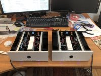
Beside a few audio cables I'd made in the past, I'm not much of a Dyi-er myself. However, I recently got my hand on a new (old) ACA V1.2 Kit (I believe it's from 2013 with "AMP CAMP #1b boards and two half-size enclosures). I very much like to give it a try and build the kit myself. I looked through the forum as well as online but I couldn't find instruction specifically for the V1.2 Kit.
The closest instruction I found on YouTube are for V1.6 or V1.8 kit. I did see a step by step photo instruction at the very beginning of this post. I understand that's for the first V1.0 kit. I'm wondering if I'll be able to follow the V1.0 instruction on my V1.2 kit (if they are close enough)? Or better yet, anyone might be able to point me to a post/manual specifically dedicate for the V1.2 kit?
Very much appreciated!
I'm a total newbie and would like to look for some help from everyone here.
Beside a few audio cables I'd made in the past, I'm not much of a Dyi-er myself. However, I recently got my hand on a new (old) ACA V1.2 Kit (I believe it's from 2013 with "AMP CAMP #1b boards and two half-size enclosures). I very much like to give it a try and build the kit myself. I looked through the forum as well as online but I couldn't find instruction specifically for the V1.2 Kit.
The closest instruction I found on YouTube are for V1.6 or V1.8 kit. I did see a step by step photo instruction at the very beginning of this post. I understand that's for the first V1.0 kit. I'm wondering if I'll be able to follow the V1.0 instruction on my V1.2 kit (if they are close enough)? Or better yet, anyone might be able to point me to a post/manual specifically dedicate for the V1.2 kit?
Very much appreciated!
Thanks Ben! That's great to know.The instructions at the beginning of this post will work for you. The only difference between the #1 board and the #1b board is that R15 (2.21k) was added to #1b.
- Home
- Amplifiers
- Pass Labs
- ACA illustrated build guide