I might not understand the math here, but am I correct to say that implementing the whole riaa in the first op amp feedback would compensate for the noise spread in the bandwidth in a more linear fashion than if you have the riaa in the second stage?You are partly correct, partly misinterpreting what S(inoise) in Fig. 1 stands for.
The noise sources vnoise and inoise represent the noise of the entire RIAA amplifier, including the termination resistor if there is one. As the termination resistor shunts the signal path, it contributes a term 4kT/Rterm to S(inoise), where Rterm is the termination resistance.
When you let Rterm approach zero, its noise current contribution goes to infinity. When you don't let it approach zero but make it some ridiculously small positive value, say 0.001 Ω, you will need to increase the amplifier's gain and change its correction to ensure you still have the correct transfer from the cartridge's Thévenin voltage (EMF) to the output. It isn't difficult to imagine that that will increase rather than decrease the noise floor.
One approximation I made in Fig. 1 is the assumption that the intended transfer from the cartridge's Thévenin voltage (EMF) to the RIAA amplifier output is given by the RIAA transfer. You could argue that to be exact, H(s) should represent the voltage division between the cartridge impedance and its recommended load, RIAA-weighting and A-weighting instead of only RIAA-weighting and A-weighting. The loading usually only has a substantial impact above 10 kHz or so, which is a frequency range that gets attenuated by both the RIAA- and the A-weighting, and I only needed a ballpark figure for the effective cartridge impedance, so I assumed my approximation to be good enough.
The main advantage of implementing the whole riaa in the first stage is achievement of the maximum dynamic range at reasonable supply voltage (with better sounds from from crackles and clicks). Along with minimizing input capacitance due to good loop gain at higher frequencies.I might not understand the math here, but am I correct to say that implementing the whole riaa in the first op amp feedback would compensate for the noise spread in the bandwidth in a more linear fashion than if you have the riaa in the second stage?

Yes, but I can increase my termination even to infinity without a problem, but TIA`s can not due to excess gain.I can see by inspection it is only 1 dB worse than your 150 kohm termination resistor, 10 dB log10(150 kohm/120 kohm) to be precise.
When you look at the RIAA- and A-weighted total noise, the 47 kohm termination is usually the biggest noise source in the amplifier. The cartridge thermal noise is of the same order of magnitude.
Yes, 47k is a stupidity. And not only because of the increased noise
Yes, the surface noise is mostly lover 1-2 kHz, but preamp hiss is higher 2-6-10 kHzWhen there is a record playing, record surface noise is usually far greater, but according to Nick it doesn't mask the cartridge and amplifier noise because of its different spectral distribution.
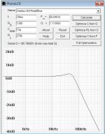
No, it's not. You can't even do 150 kOhm because you'll get a peak in the frequency response with parasitic input capacitance. The graphs below show that at Rin = 150 kOhm, even 50 pF causes a peak. Lossy cartridge model used, simple with L and R will give even more peak. To get low parasitic capacitance, the amplifier must be placed inside the turntable. But this is a serious limitation, the modern high-end means the phono stage as a separate beautiful device. With a capacitance of 100 pF (this is the actual capacitance of the cable), Rin can be a maximum of 75 kOhm. For TIA, there are no problems with cable capacitance.Yes, but I can increase my termination even to infinity without a problem
Attachments
Last edited:
You're utterly and repeatedly wrong no matter what people say and you can't be moved by anyone cause you're the only designer in the world who got it right...Yes, the surface noise is mostly lover 1-2 kHz, but preamp hiss is higher 2-6-10 kHz
The human ear is most sensitive btw 500...2khz!
Also that noise is provoking thd and imd by itself in the upper band. You cannot ignore it unless the riaa encoding decoding system does by itself or the vinyl signal is helping us which the 45rpm does better than 33 rpm.Do you think 45rpm records appeared just by chance because the DJ just liked to carry more record with him and build some muscles?
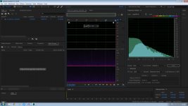
If we talk about surface noise, I was very impressed that it drops noticeably with a decrease in the separation of stereo channels in the low-frequency region. I really want to add a filter with L-R signal processing.
Yes, it is attached both in flac and jpgIf we talk about surface noise
Attachments

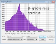
You just have some kind of mess in your head, imho. Sorry, do not insinuate my messages. Simply compare typical attached groove spectrum with noise spectrum of phono preamp.The human ear is most sensitive btw 500...2khz!
Also that noise is provoking thd and imd by itself in the upper band. You cannot ignore it
Attachments
Last edited:
My preamp v.4 and v.5 [ https://www.patreon.com/posts/su-xxi-v4-2-i-s-71350056 ] has 12 pF input (with jfe2140 jfets) and mounted near tonearm without any parasitics. 😏 I have no any significant peak even with 270k both in audio @20 kHz and ultrasounds. Аnd no hemorrhoids with any tau adjustments for the used cartridge...No, it's not. You can't even do 150 kOhm because you'll get a peak in the frequency response with parasitic input capacitance.
Attachments
Last edited:
This is just the input capacitance of the amplifier. There is also the capacitance of the tonearm wires and the parasitic capacitance of the cartridge itself. Try to inject the sound card signal into the cartridge circuit and get the real frequency response.My preamp v.4 and v.5 has 12 pF input (with jfe2140 jfets)
Yes, this option is also possible. My efforts are focused on creating a circuit that could work with interconnect cables.and mounted near tonearm
All this is good, but when I short-circuit the leads of the electric motor of a child's toy, it becomes much more difficult to rotate it. I hope, but not sure 😏, loading a cartridge with zero virtual input impedance will work differently and the Lorentz electromagnetic force will be inactive here 🤔For TIA, there are no problems with cable capacitance.
Last edited:
It would be great, it would be possible to dampen the mechanical resonance. But, unfortunately, this is not the case. The cartridge has a very low efficiency of converting mechanical energy into electrical energy and vice versa (less than 0.1%, you can calculate the output power and mechanical movement of the mass of the moving system). Shorting the winding will not affect the movement of the needle in any way. Even if you apply current to the winding, you are unlikely to detect the movement of the needle.All this is good, but when I short-circuit the leads of the electric motor of a child's toy, it becomes much more difficult to rotate it. I hope, but not sure 😏, loading a cartridge with zero virtual input impedance will work differently
I quoted your words telling "the noise density is mostly 1..2khz" .Your attached photo shows the noise mostly below 100 hz which is completely wrong again unless you have -12db rumble from the turntable and no PSRR in the phono preamp itself. That's highly unrealistic.You just have some kind of mess in your head, imho. Sorry, do not insinuate my messages. Simply compare typical attached groove spectrum with noise spectrum of phono preamp.
Please stop using insulting words for nothing!
You could apply a few volts of dc on the coils as in stepping motors if the coils could withstand the current.The cartridge has a very low efficiency of converting mechanical energy into electrical energy and vice versa (less than 0.1%, you can calculate the output power and mechanical movement of the mass of the moving system). Shorting the winding will not affect the movement of the needle in any way. Even if you apply current to the winding, you are unlikely to detect the movement of the needle.
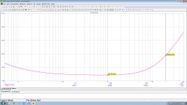
Attached is a real groove noise of LP. Analyze its spectrum and see for yourself that I am right. You can also digitize your own groove noise for a minute and compare with mine.I quoted your words telling "the noise density is mostly 1..2khz" .Your attached photo shows the noise mostly below 100 hz which is completely wrong again unless you have -12db rumble from the turntable and no PSRR in the phono preamp itself. That's highly unrealistic.
Attachments
Your idea of eliminating the negative capacitance effects of interconnects in this way is really noteworthy. But in addition to the capacitance, the long cables also add interference with pickups; however, here the virtual earth will also give a positive effect. The only bad thing is necessity of L/R tuning for each cartridge.My efforts are focused on creating a circuit that could work with interconnect cables.
I trust his messages, but please specify where exactly this message isI think @billshurv looked into that once.
- Home
- Vendor's Bazaar
- Nick Sukhov SU-XXI MM Phono stage -85 dBA SN ratio...