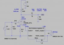
If you want to use R.C. regulator for filament biased DHT tube, the below aspects are interesting:
1.) Bias voltage: Rbias*filament current + about half of filament voltage;
2.) Filament current;
3.) Raw DC for R.C:
Rbias*filament current + filament voltage + 5-6V headroom for R.C. regulator.
The most important thing is voltage on Rbias (in this case 15R). If the filament current has perfect value (for example 325mA), the voltage will be -in this case- 5.32V.
p.s.
The old DHT tubes filament -hot, after 5-10 min heating- resistance is variable from one piece to another, if it does not differ (i.e. filament voltage does not differ at definite current) more than 20% from datasheet value, it's OK.
Underheating (for example in this case 300..310 mA) is acceptable, improve SQ.

1.) Bias voltage: Rbias*filament current + about half of filament voltage;

So then in the case above,
Bias voltage is 0.355A * 15 Ohm + 2.1V = -7.42V ?
3.) Raw DC for R.C:
Rbias*filament current + filament voltage + 5-6V headroom for R.C. regulator.
Rod has mentioned about 2.6V of headroom in his instruction. so is 5-6V better sounding?
Would you recommend having -8V or -9V of bias for 4p1l?BTW. such (#1780) low bias -for me- only acceptable if the anode load is CCS, else distortion would be growing.
What's the load of 4P1L?
CCS, gyrator, transformer, resistor .....
If the last two, how many the impedance?
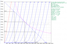
For preamp the "recommended" anode current is 25..40mA.
Desired anode current and estimated anode (relative to cathode) voltage determinates operating point.
This operating point -on trioded curves- and load (impedance) defines working range.
Sample:
CCS, gyrator, transformer, resistor .....
If the last two, how many the impedance?
For preamp the "recommended" anode current is 25..40mA.
Desired anode current and estimated anode (relative to cathode) voltage determinates operating point.
This operating point -on trioded curves- and load (impedance) defines working range.
Sample:
Attachments
What's the load of 4P1L?
CCS, gyrator, transformer, resistor .....
If the last two, how many the impedance?
Resistor 5700 Ohm
Preamp/buffer
I can do any anode current from 210V to 240V/245V
25/30ma would be better. i do not have a big headroom in a transformer
Last edited:
With a 4P1L I and others found it sounds fuller at 25mA up to 35mA, otherwise it was a trifle skinny sounding. So that points to a plate choke or CCS rather than a resistor. The 2P29L sounds nice with a resistor which if you have 300v B+ can be around 12mA. I like resistor loads - they sound purest to me for the timbre of acoustic instruments and voices, so I use 2P29L in preference, or indeed 10Y or 46. But as Bela says, a resistor is not viable for the 4P1L unless you have very high B+ which is unlikely and un-needed.
Yes, that's correct for the V9 Regulator. With low current (325mA) it's OK if the voltage is a little higher, too.and Coleman regulator should have 5.32V + 4.2V = 9.52V
Am I right?
The bias calculations from euro21 are perfect.
sorry, B+"210V to 240V/245V"
Anode voltage or B+?
thank you so much..IMHO R loading is the worst scenario.
BTW see my #1765 post.
it looks like the second pic is closer to my case.. but with a 2.1V filament supply
so, 0.65*6.8+1.1V or - 5.52V bias for resistor load, right?
Sorry for the many questions, I have a battery-based bias -3.3V now.
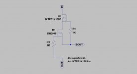
what is the "cascode CSS"? I do not find anything in google
Last edited:
Voilá.what is the "cascode CSS"? I do not find anything in google
Attachments
it seems that with a resistor load more than 22-23mA can not be squeezed out. and it is necessary to switch to a non-resistive 4p1l load.But as Bela says, a resistor is not viable for the 4P1L unless you have very high B+ which is unlikely and un-needed.
CCS as I understand it is a subtype of non-resistive load. Isn't it?
Are there ready-made, proven boards to buy?
please, could you share the schema with LL1671?the best sound i get is use of Lundahl trafo LL1689 or LL1671 25ma
thank you so much Rod!Yes, that's correct for the V9 Regulator. With low current (325mA) it's OK if the voltage is a little higher, too.
The bias calculations from euro21 are perfect.
CCS is the high impedance constant current "device".Are there ready-made, proven boards to buy?
It's requires -about- 30-40V higher voltage as anode voltage+estimated swing peek.
If you use it as anode load of preamp tube, the B+ must be -at least-
Ua+ 10...20V (swing) + 30V (headroom).
Are you know Ale's site?
https://www.bartola.co.uk/valves/
CCS board:
https://www.bartola.co.uk/valves/for-sale/ccs-pcb/
Hagerman uses the Hammond 157G choke as a load in his Tuba headphone amp. That's 30H at 40mA so very usable with the 4P1L.
He used it with EL84 in triode. Cheap solution, but works.
https://hagerman-audio-labs.myshopi...products/tuba-vacuum-tube-headphone-amplifier
He used it with EL84 in triode. Cheap solution, but works.
https://hagerman-audio-labs.myshopi...products/tuba-vacuum-tube-headphone-amplifier
How to calculate 11mA from? Thank youAndy,
If you see the EL12n datasheet, the -recommended- bias is -7.5V (250V a-c, 72mA anode, 11 mA G2 current, 90R cathode resistor), so any driver tube fulfils 15Vpp swing (about 3-5x gain).
Sample:
View attachment 1067128 View attachment 1067134
- Home
- Amplifiers
- Tubes / Valves
- 4P1L DHT Line Stage