I will contact Rod and see if 10.5V AC is enough for his regulators, and then this would seem like a great approach. Thanks!Ahh, yooze an engineer. (I'm not!) Your 'speech' was pretty unassuming and a bit hard to judge where you were coming from so I felt cautious about egging you on.
By Rod's general info sheet, you want a minimum of 3.5VDC for the Coleman reg. - Nominal 4.2VDC (and Max 7.)
This is where I was interested in your secondary's current capability as for a bridge rectified output for 3.25A I think you'd want it rated for something just under 5.5A at least. (I divide by .62 as from Hammond's recommendations)
It's nice to see all the room you have in there though. From the picture it looks like you could fit an R-core or toroidal power transformer quite easily.
I do agree that Rod's regulator is a very good way to do it (they're on heatsinks in the 211 breadboard pic below), but I have a thing about people being dissuaded from checking things out for themselves so had to chime in. Once you've got it off the shelf and if you have the time, I still think it's worth trying before you go to something more sophisticated.
With a simple on line calculator I think the recommended diodes generate 13.6V and then it's down to the loss through R1 and R2 which if I use a (very) small R value should allow the remaining Raw DC to be near to the nominal.
That the real-world effectiveness of cancellation in PP stages is not always as good as expected.On careful looking at this graph, the +/- 50 Hz side bands are the most prominent. The +/- 100 Hz bands are pretty benign at -70 dB. What does it prove?
Quite right, Ian! Measuring, as well as listening, for preference.but I have a thing about people being dissuaded from checking things out for themselves so had to chime in.
How do those big transmitters sound?
It's a little close. It will depend on the current (or VA) rating of the transformer, and the open-circuit voltage.I will contact Rod and see if 10.5V AC is enough for his regulators, and then this would seem like a great approach. Thanks!
Send me a PM with details & email address, and I will forward the best possible solution.
Given that the tube has a thoriated tungsten filament, one optimisation that is very useful in this case:
controlled reduction of the filament voltage. Run at 9.5V, and gain another 0.5V in headroom for the regulator.
This has two benefits: Gives more overhead to work with - and makes the tube last much longer.
The picture is from an Eimac application note (AB-18, 2010 revision). It shows how stabilizing the filament voltage at -5% of nominal (after the burn-in phase) can potentially extend the tube's lifetime by more than double, compared to running at nominal Vf.
As the emission starts to become exhausted (indicated by lower output, or increased distortion), the filament voltage is adjusted, in steps, at the end of the tube life, to extract the last drops of performance ( and serves as a warning to locate new tubes!)
Given the ±5% or even ±10% Line voltage tolerance (in Europe + other countries), this is not a viable option with AC-heating. Considering the cost of replacing transmitting tubes, allowing Vf to wander around with the (AC-heat) Line voltage is a wholly false economy.
Apologies for re-posting this fragment yet again, but it is essential information.
Hi Rod,
Yes, reducing heater / Filament voltage has a similar effect in all tubes, and lamps as well. No surprises here. I completely agree with you on giving the regulator more headroom while extending tube life. It just simply makes sense to do this.
Yes, reducing heater / Filament voltage has a similar effect in all tubes, and lamps as well. No surprises here. I completely agree with you on giving the regulator more headroom while extending tube life. It just simply makes sense to do this.
These conventional approaches improved but didn't reduce hum to DC levels. Neither positive or negative filament bias fully worked. As per the classic TungSol paper the latter appeared the most effective. It's possible this particular tube running relatively hot is a special case. More relevant to the thread than specific techniques is the measured and outsize audible impact of a low level 'broadband' hum/buzz, for me well in excess of expectation.I would have biased the heater positive to around 35 VDC myself using AC heaters.
One solution if to wire the output tube heaters opposite each other as far as polarity and swap them every few months.Hey - thanks everyone for the help and thoughts so far.
DC may have some issues on long term life of tubes, BUT this is not a serious problem.
I've used A/C heaters on a 2.5V heated DHT (47 tube) and heard no hum on my 94db speakers. It does simplify the circuit not using DC. I've read as the voltage increases, so does the hum problem. I used DC on my 300B amp to try avoiding the problem, but never tried AC for the heaters on that amp.
Good !How do those big transmitters sound?
The project centres on a set of output transformers I got about 15 years ago from a winder who gave them to me explaining that their general design was for transmitters but that these ones were wound without starting one of the HV leads on the inside of the winding - something done for safety in high voltage radio circuits. He said that because ordinarily the windings had go over top of the heavily insulated lead it distorted the symmetry and for audio it would be better without.
So, because of all that, they came with being asked to promise him I would not take the voltage up to usual transmitter territory.
The challenge as I saw it was that while they're not rated for transmitter voltage, they are good for the power. It took ten years for it to dawn on me that both A2 and Grounded Grid operation were the answer. A2 because you can get the swing without the centre voltage being that high , and grounded grid (in common use by HAMs) because the power of the driver will add to the power at the plate of the output tube. (You also don't need to think about supplying the grid current)
I was a bit unsure I was on the right track at first, - Crowhust did wonder why nobody in the audio world was interested. That was seventy years ago and nothing much seemed to have changed in all that time. - but eventually I started seeing posts from Tubelab about his UNSET and SpreadSpectrum's on his Corona Amplifier and that they were both dealing with driving the cathode made me feel I was in very good company and happy to keep going.
To date, this thing runs with B+ of only 550VDC but with the 814 driving the 211 cathode it has a really nice solid sound , very even frequency response and surprising clarity of detail. I'm very happy with it so far. Some more work to do on it tho'.
Thanks for asking. I wasn't sure I'd ever get the chance to talk about it. It's been a long interesting project with lots learned.
With the problems grounded grid solves and the sound it makes it's curious that it isn't considered more (for power stages) .
Last edited:
Very few huge-tube-audio transmitters still in use.How do those big transmitters sound?
Most mature AM broadcast xmitters ran NFB around the whole rig (from RF out thru detector to audio in) which is maybe 8-12dB of hum and IMD reduction.
The really huge rigs (several in every city) had 3-phase filaments. Now what do we hear???
Three phase power is generally easier to filter than single phase since once rectified the output never drops to zero and there are three pulses per output cycle.Very few huge-tube-audio transmitters still in use.
Most mature AM broadcast xmitters ran NFB around the whole rig (from RF out thru detector to audio in) which is maybe 8-12dB of hum and IMD reduction.
The really huge rigs (several in every city) had 3-phase filaments. Now what do we hear???
Remember alternator whine in your 8 track car stereo? The alternator in a car is a 3 phase AC generator feeding some rectifier diodes. The rotor is the electromagnet and the three windings that make up the stator is the source of output power. The car's battery is the filter cap. Some are Y configured, some are Delta. The alternator spins at about twice the engine speed due to its smaller pulley. The spinning electromagnetic rotor has multiple poles so there are 2 to 5 complete AC sine waves per winding in one revolution. Each is 120 degrees out of phase with it's neighbor. This puts the raw AC in the middle of the audio frequency range and dependent on engine RPM. Early alternators produced a near sine wave, but as time passed and cars needed more and more power to run the rotor poles were shaped to produce a nearly square output waveform.
Yeah; even generator whine. But I never had a 3-phase filament 8-track, where the "filtering" on the filament was mostly summation.Remember alternator whine in your 8 track car stereo?
Rectified 3-phase is similar but different. More high harmonics. Straight 3-phase AC heat is a dull hum. Sounds "more powerful" than 1-phase AC because 3rd harmonics.
I did not know WLW-AM, in 1962, proposed running 750 kilowatts (50% more than their "experimental" level of 500KW in 1934, which aroused world-wide protests but also taught Moscowites to speak with an Ohio flavor).
This raises a question: because the new switching-MOSFET bridge rectifiers need additional higher voltages, that must be derived from the AC source anyway, would there be any advantage to Coleman type regulators by using these extra voltage sources (for lower level stages) to minimize required regulator overhead? Leading to an integrated rectifier/regulator.It's a little close. It will depend on the current (or VA) rating of the transformer, and the open-circuit voltage.
Send me a PM with details & email address, and I will forward the best possible solution.
Much thanks, as always,
Chris
Since they have a 3-phase supply they should be able to use quadrature heating for any directly heated parts.The really huge rigs (several in every city) had 3-phase filaments. Now what do we hear
Common on 3-phase rectifiers before silicon. 🙂
Hi Chris, the control voltage section works at low voltage, and doesn't force a high overhead - a definite design choice. The headroom does permit very low noise levels (typically <10µV rms, 20-20kHz, for 300B), which is usually desirable, and essential for filament bias. Having said that, I have another circuit to hand that works quite a bit lower.This raises a question: because the new switching-MOSFET bridge rectifiers need additional higher voltages, that must be derived from the AC source anyway, would there be any advantage to Coleman type regulators by using these extra voltage sources (for lower level stages) to minimize required regulator overhead? Leading to an integrated rectifier/regulator.
Much thanks, as always,
Chris
The difficulty with integrated rectifier solutions is the conflict of location: the regulator output should be near the tube socket for short wiring; but the rectifiers & capacitors must be close to the PT, or there will be a notable risk of the rectifier pulses - carried by long wiring - coupling into signal wiring and parts. So I have always kept the Raw DC as a separate module.
If you're getting good results at 550V supply and grounded grid, it certainly merits attention. I fixed up a friend's Fender guitar amp once, that did something similar, with the output tubes driven by big NPN transistors. But that's a different kind of sound, I suspect.With the problems grounded grid solves and the sound it makes it's curious that it isn't considered more (for power stages) .
Don't remember a Fender amp with a hybrid output stage but there were some Music Man amps with an NPN BJT in the cathodes of grounded grid 6L6GC or 6CA7 tubes. Some made over 100 watts. There were several cases of flaming Music Man amps in south Florida in the 80's but that was likely due to stupid high plate voltages and high humidity, rather than the output stage tech. Music Man was a company that Leo Fender ran after selling Fender (the company) to CBS in the early 70's. Music Man was sold to Ernie Ball (the guitar strings company) sometime in the 80's.If you're getting good results at 550V supply and grounded grid, it certainly merits attention. I fixed up a friend's Fender guitar amp once, that did something similar, with the output tubes driven by big NPN transistors. But that's a different kind of sound, I suspect.
Being a long time ham radio operator I knew about and had previously experimented with grounded grid RF amps long before coming up with UNSET. In a pure grounded grid design the grid current during A2 or AB2 operation flows through ground when the cathode is driven negative. UNSET uses no negative supply and resistive feedback is applied to the grid. The current for A2 must flow through the resistive feedback divider. A2 is not needed or wanted with TV sweep tubes but may be beneficial with common audio tubes. In this case the ground end of the resistive divider is tied to a positive supply.The challenge as I saw it was that while they're not rated for transmitter voltage, they are good for the power. It took ten years for it to dawn on me that both A2 and Grounded Grid operation were the answer. A2 because you can get the swing without the centre voltage being that high , and grounded grid (in common use by HAMs) because the power of the driver will add to the power at the plate of the output tube. (You also don't need to think about supplying the grid current)
I never meant to imply they were on par.Being a long time ham radio operator
Me being at least an arbitrary 83.6 levels below your knowledge grade and able to focus on only one electrode at a time, my level of comprehension was , more or less, "Me drive cathode . . . . . . . Hey! He drive cathode too! . . . . . . . Me do good ! . . . . . . Me be famous !"
My comment was kind of a fishing operation, any folks with power engineering in the crowd? Looks like maybe not.quadrature heating
Quadrature heating of the cathode was used with gas & mercury rectifiers to solve a cathode emission problem.
The drop is usually only 8V. So that even tho the potential across the length of the cathode is at max 2,5*root of 2,
in a single phase circuit most of the current will always come from the same end.
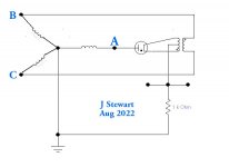
That problem can be minimized in a 3-phase system. In the diagram, if phase A is to be rectified a voltage 90 degrees
out of phase can be obtained using a step down transformer across the ends of phase A & phase B.
And similarly for the other phases.
But there would always be six rectifiers in a full bridge, The simple diagram here makes poor use of the copper & core
of the transformer. A figure of merit called 'Utility Factor' by people who design transformers, for power in particular.
A resistive load with no rectifiers gets a rating of One.
Quadrature heating of this kind would never be used in an audio amplifier circuit. Except maybe the rectifiers! 🙂
Put this in your file of 'May As Well Know'.
Attachments
I have an 845 amplifier driving fairly efficient speakers. I had to resort to a pair of 3.5 MH input chokes for the filament supply to get the output totally quiet.Why not include a choke in the AC supply with bypass capacitors? Very effective.
Also I am running mine at abut 9.5 volts on the filaments.
Correction- That should be Phase B & Phase C.😱In the diagram, if phase A is to be rectified a voltage 90 degrees
out of phase can be obtained using a step down transformer across the ends of phase A & phase B.
- Home
- Amplifiers
- Tubes / Valves
- AC Heater for better Sound quality? Waste of time or worth a try