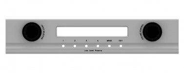
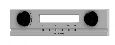
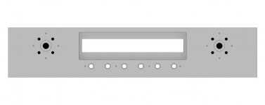
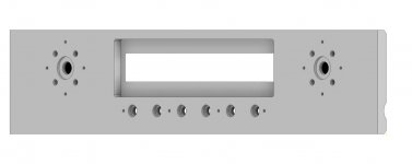
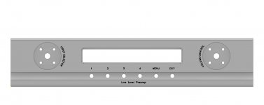
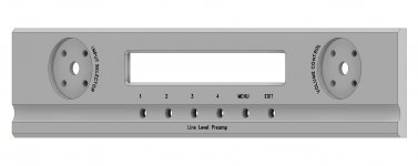
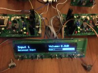
A few users asked about the drawings for the front panel that uses dual encoders and also the push buttons.
I use 50mm cnc made alluminium knobs from aliexpress(you can search for them by searching exactly what i wrote), the push buttons are the same as the ones Ine uses(he placed the link here in the past). The display extrusion is 1cm(5mm on each side, the ir receiver head has 5mm) wider than both displays this way I can solder the ir sensor directly on the pcb and I don`t need an extra hole in the front panel(keeps also the symmetric front panel look).
I am attaching some last screenshots and also the dwg and dxf files so you can order your own front panel. For the dwg and dxf files you have to rename them and remove the rar extension.
Any suggestions will be more than welcome 😉
Thanks
Attachments
-
 1.jpg53.2 KB · Views: 204
 -
 2.jpg53.5 KB · Views: 198
 -
 3.jpg13.5 KB · Views: 180
 -
 4.jpg32.5 KB · Views: 173
 -
 5.jpg38.2 KB · Views: 164
 -
 6.jpg47.5 KB · Views: 170
 -
 7.jpg58.3 KB · Views: 175
 -
 8.jpg32.2 KB · Views: 169
 -
 9.jpg42.2 KB · Views: 195
 -
ugs pre dual encoders w pushbuttons silver.dwg.rar177 KB · Views: 147
-
ugs pre dual encoders w pushbuttons silver.dxf.rar617.7 KB · Views: 170

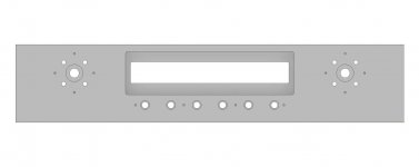
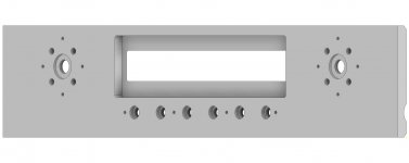
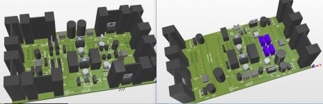
Two, if you can do the buttons and three if you can't.Here you can easily compare the differences and which one you like most. After drawing all 3 versions I am quite undecided why way to go.
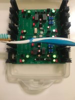
Today I received 2 cinemag cmoq-4h trafos and wired them to accept differential and single ended signals like Zenmod shown in his Iron preamp thread.
The source was my dac with 200r output impedance wired as balanced, as load I used a 10k resistor.
There was nothing else connected.
To be honest I remained a bit surprised what the trafos can do.
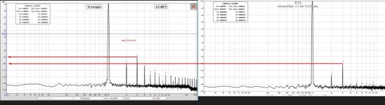
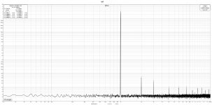
I am attaching a screenshot with the ugx on the left and the transformer on the right.
They both have ~14v on the output.
Ugx gain is ~10db, transformer gain is ~6db.
The source was my dac with 200r output impedance wired as balanced, as load I used a 10k resistor.
There was nothing else connected.
To be honest I remained a bit surprised what the trafos can do.
I am attaching a screenshot with the ugx on the left and the transformer on the right.
They both have ~14v on the output.
Ugx gain is ~10db, transformer gain is ~6db.
Attachments
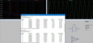
It looks like this.
When you feed se signals you need to cut out R2.
Hopefully in the near future I will draw a pcb for the ugs muse preamp that will use these transformers as voltage gain stage instead of the now very expensive and hard to find Toshiba complimentary jfets and mosfets. I don`t know why but I have a feeling that this will replace my UGX.
Will keep you posted as soon as I have something to share.
Attachments
Very nice! Had you previously done a single encoder version? I seem to recall that, will have to go back and look.A few users asked about the drawings for the front panel that uses dual encoders and also the push buttons.
I use 50mm cnc made alluminium knobs from aliexpress(you can search for them by searching exactly what i wrote), the push buttons are the same as the ones Ine uses(he placed the link here in the past). The display extrusion is 1cm(5mm on each side, the ir receiver head has 5mm) wider than both displays this way I can solder the ir sensor directly on the pcb and I don`t need an extra hole in the front panel(keeps also the symmetric front panel look).
I am attaching some last screenshots and also the dwg and dxf files so you can order your own front panel. For the dwg and dxf files you have to rename them and remove the rar extension.
Any suggestions will be more than welcome 😉
Thanks
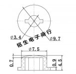
Also, was poking around and found these pushbuttons, which I may use for mine. 9.7x6.6mm
https://www.aliexpress.com/item/325...00029293262807!sea&curPageLogUid=Jq75GiE37cc2
I did draw a single encoder version but shared only a screenshot of that. I did it mostly to be able to compare it with the other versions.
The single encoder version is not my design and will not share it without Ine’s permission.
The buttons you want to use seem to have different dimensions between the different models which seem different again than the ones for which the holes are drawn.
There are a few models that look fine and can go quite ok with a black or silver front.
If you want to use something different than what the drawing includes I suggest getting first the parts and measure them with the caliper and proceed only after that. Once having the right dimensions it takes close to no time to do the modifs which I can help you with.
I am attaching a photo with the buttons (SC102) for which the front panel is drawn.
Attachments
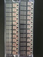
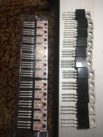
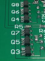
I didn’t manage to order the enclosure yet but instead I had been busy with drawing the pcb for my new UGT transformer line stage.
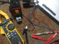
For this one I think I will use some Fairchild mosfets that I already have at hand and save the Toshiba octets for something else. I tried to match these at 55c and for the required current(27ma) I got pretty close matches.
To control the temp I used a small pid relay and a 200w heating plate.
For this one I think I will use some Fairchild mosfets that I already have at hand and save the Toshiba octets for something else. I tried to match these at 55c and for the required current(27ma) I got pretty close matches.
To control the temp I used a small pid relay and a 200w heating plate.
Attachments
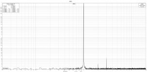
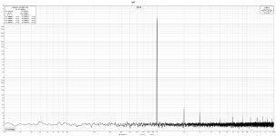
Still have to tweak it a bit but overall I am quite pleased. I finished it for a while but to exclude being biased by the measurements, I enjoyed the sound for some time and only now I measured the performance.
I like very much the fact that even it’s balanced on the output you get a nice thd profile with h2 dominating. At this moment it has a gain of 5db.
I like very much the fact that even it’s balanced on the output you get a nice thd profile with h2 dominating. At this moment it has a gain of 5db.
Attachments
-
 F68AFB4B-8D3A-48F4-BF44-D4BC4BC6A941.jpeg288.4 KB · Views: 244
 -
 C2034197-372C-440D-8FD8-1F774EB9CB75.jpeg315.8 KB · Views: 262
 -
 BF18498F-D5E5-4661-8454-A5BB5E9657B6.jpeg499.3 KB · Views: 257
 -
 2B97E94E-9CAB-41AF-8E16-65573B830FEB.jpeg246.2 KB · Views: 234
 -
 AD9D7724-B95D-4A6D-97BE-18AFDA7E96B0.jpeg247.6 KB · Views: 228
Anyone has by chance ready made heatsink modules for the UGS/buffer modules?
Thanks a lot and keep up the good work.
By now I pretty much finished everything and will be powering and flashing the uC next and starting on the case in parallel.
Thanks a lot and keep up the good work.
By now I pretty much finished everything and will be powering and flashing the uC next and starting on the case in parallel.
Those are available in black as well, just got some from the same seller.Here the SC102 knobs that Ine used:
https://de.aliexpress.com/item/1005002085295869.html
As I see it the heatsink is used more to stabilize the offset than to cool the fets.
Give it a try without, in an enclosure and see if you really need it.
Give it a try without, in an enclosure and see if you really need it.
Interested as wel.@Ine sorry for disturbing, what standoff height did you use for the mcu board?
Generally, the less the distance between glass and the OLED displays, the better the display will look like.
Then the height of the tactile switches used need to match and also to where the button caps are placed on the backside of the front panel. I was just beginning to look at this as I am about to design the front panel and need to order the proper tactile switches as well.
On the pics above it looks like you already made a decision and soldered the switches and mounted spacers?
Hi 🙂@Ine sorry for disturbing, what standoff height did you use for the mcu board?
Really can't remember .I built this pre-amp back in 2016 !!. But if I rembeber right ?, the standoffs were 5mm, and the tactile switches 16mm.
10mm thick faceplate?Really can't remember .I built this pre-amp back in 2016 !!. But if I rembeber right ?, the standoffs were 5mm, and the tactile switches 16mm.
- Home
- Amplifiers
- Pass Labs
- UGS-muse preamp GB