Oh yes,That’s great! Thanks. Now we can build, measure and play too!
let me know
You will find many simple push pull EL84 amplifiers (and many simple push pull 6BQ5 amplifiers).
Many will work, many will work very well.
Some schematics are not tested (some of those will not work, and some of them Will work).
The simplest push pull ones are probably the self inverting amplifiers.
But first define simple.
Easy to build
Least number of parts
Easy to understand
Easy to get the parts
Easy to design the proper parameters for a given schematic
Etc.
I have built several self inverting push pull amplifiers.
I used a resistor, then a choke, then a bipolar NPN circuit for the output tube cathodes bias/coupling to get the self inverting effect.

There's so much offtopic here.
So anyone built this minimalistic creation?
I'm looking to build at first a guitar amp and would definitely want to try what a guitar sounds like through such minimalism, that's why saturation wouldn't matter to me. The simpler it is, the better, I'd just like to try push pull and make it amplify sound.
As I can see, yes the preamp is missing. Would it be okay to take any guitar preamp and connect it to that power section as is?
John Broskie of Tube CAD published a simple EL84 push-pull design some time ago and it was discussed in a thread here on diyAudio. You can read that thread here:
https://www.diyaudio.com/community/...-the-tubecad-journal-site.171386/post-2263848
https://www.diyaudio.com/community/...-the-tubecad-journal-site.171386/post-2263848
cooloox,
I believe there are a number of persons that have built the amplifier you presented in Post #1.
Of course, it has to be built with the input stage that others mentioned, like in Post # 2.
300V B+ should work well.
Depending on the output of your electric guitar, you might find that the input stage does not have enough gain, so you might need one more stage of amplification ahead of that amplifier's input stage to get reasonable volume, otherwise it would be a nighttime practice amp.
And, depending on the efficiency of your speaker, you might not have enough power to be able to play as loudly as you would like, but at more moderate sound levels should work very well.
I wish I had the parts and the time, I would build that amplifier just as in the complete schematic that includes a current sink of the two output stage cathodes, instead of the resistor.
I would probably use a choke as both the current sink and self bias for the EL84 tubes.
Depending on the B+, and the choke DCR, It might need a series resistor between the choke and the cathodes to get the proper bias voltage and cathode current.
Use a resistor first to get the proper bias voltage and cathode current. Then replace that with a choke, and a series resistor so that the choke DCR and series resistor are equal to the resistor value you used that gave the proper bias V and cathode current.
I liked the choke current sinks the best on the self inverting amplifiers I built. Simple and effective.
Be Sure to use very well matched EL84 tubes (Eurotubes.com extensively re-tests all the JJ tubes that they get from JJ in Slovakia; and the matched tubes are Very well matched). Eurotubes does ship to many countries outside the US.
JJ makes the ECC99, it is a dual triode, so if you need more gain, you already will have the triode for an input stage.
Darn, . . . another project for me, just what I do not need, I am too busy.
But I might drive over to Eurotubes and pick up a pair of JJ EL84 tubes.
I was already looking for a way to use a chassis that is single ended now; and instead put a simple push pull amplifier on that same chassis.
Do not use a magnetic steel chassis, use aluminum.
Orient the power transformer and B+ choke coils so they are 90 degrees different from both the output transformer and cathode current sink choke.
Use lots of space (distance) between the output state transformer and choke; versus the location of the power transformer and B+ choke.
Let us know how it works out for you.
Happy Building, Happy Listening, have fun.
Last edited:
I see nothing bad using a steel chassis.Do not use a magnetic steel chassis, use aluminum.
Orient the power transformer and B+ choke coils so they are 90 degrees different from both the output transformer and cathode current sink choke.
Use lots of space (distance) between the output state transformer and choke; versus the location of the power transformer and B+ choke.
My re-designed Magnavox 9304 amp chassis (schematic above) is on it's original 8x12x1.5" steel chassis.
And for decades amps and tuners were on steel, even high-end models.
My amp has absolutely no issues, dead quiet ear-to-the-speaker.
Yes, this is just about the simplest push-pull circuit you can build. Yes you can take any preamp you like, and hook it up to the power section.There's so much offtopic here.
The simpler it is, the better, I'd just like to try push pull and make it amplify sound.
As I can see, yes the preamp is missing. Would it be okay to take any guitar preamp and connect it to that power section as is?
Attachments
Thanks for the relevant reply!Yes, this is just about the simplest push-pull circuit you can build. Yes you can take any preamp you like, and hook it up to the power section.
Simple is good, I've preached that many times.Yes, this is just about the simplest push-pull circuit you can build. Yes you can take any preamp you like, and hook it up to the power section.
However, that circuit, having an ultralinear tap in use with a grounded grid design, goes against traditional designs.
It's like putting cheap tires on an expensive automobile.
Yes, very simple.But now you need a 18Vpeak input voltage.Yes, this is just about the simplest push-pull circuit you can build. Yes you can take any preamp you like, and hook it up to the power section.
Why not a serial PP. Without the triode in front 9Vpeak in. And a more simple OPT.
Mona
Attachments

Mona,
Your Post # 31:
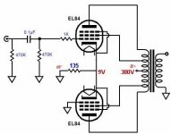
What I see is the topmost EL84 cathode pulling the bottom of the primary up, and the bottommost EL84 plate pulling the primary down (through a 135 Ohm resistor).
I do not believe that I understand that topology very well.
It does a push and a pull, but perhaps from different impedances.
Since there is very little DC through the primary, perhaps it can be a push pull transformer, or a special transformer. (those two types of transformers do not have air gaps; instead interleave the E's and the I's; in order to get the most inductance given the number of turns and the size of the laminations.
The only DC current through the primary is the topmost EL84 screen. If the transformer will not saturate with the amount of screen current, then the laminations do not have to be air gapped.
Your Post # 31:
What I see is the topmost EL84 cathode pulling the bottom of the primary up, and the bottommost EL84 plate pulling the primary down (through a 135 Ohm resistor).
I do not believe that I understand that topology very well.
It does a push and a pull, but perhaps from different impedances.
Since there is very little DC through the primary, perhaps it can be a push pull transformer, or a special transformer. (those two types of transformers do not have air gaps; instead interleave the E's and the I's; in order to get the most inductance given the number of turns and the size of the laminations.
The only DC current through the primary is the topmost EL84 screen. If the transformer will not saturate with the amount of screen current, then the laminations do not have to be air gapped.
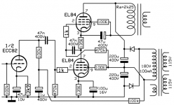
Well, it's an SRPP but with pentodes.
The result is that the cathode current of the top tube is less then the bottom one, the screen current of the bottom tube is missing. So, perhaps the cathode resistor of the top one should be a little bigger (150Ω ?).
Or making the AC and DC conditions of the top tube independent, like this.
Mona
The result is that the cathode current of the top tube is less then the bottom one, the screen current of the bottom tube is missing. So, perhaps the cathode resistor of the top one should be a little bigger (150Ω ?).
Or making the AC and DC conditions of the top tube independent, like this.
Mona
Attachments
where are the test lab of this circuit?Well, it's an SRPP but with pentodes.
The result is that the cathode current of the top tube is less then the bottom one, the screen current of the bottom tube is missing. So, perhaps the cathode resistor of the top one should be a little bigger (150Ω ?).
Or making the AC and DC conditions of the top tube independent, like this.
Mona
And why someone must have the life so complicated?
Walter
Challenge is fun?where are the test lab of this circuit?
And why someone must have the life so complicated?
I certainly understand you argument. There are times when what is needed is a well designed and tested plan to follow. But sometimes the journey is the goal and the process of thinking about how you could make something work even if it is a non-optimal and untested has it's own rewards.
The AC15 is pretty minimalist as far as PP EL84 guitar amps go:I'm looking to build at first a guitar amp and would definitely want to try what a guitar sounds like through such minimalism, that's why saturation wouldn't matter to me. The simpler it is, the better, I'd just like to try push pull and make it amplify sound.
Attachments

Simple is good, I've preached that many times.
However, that circuit, having an ultralinear tap in use with a grounded grid design, goes against traditional designs.
It's like putting cheap tires on an expensive automobile.
I'd omit the UL taps, I think the author mentions the possibility on his site. I have a soviet old radio that is not in working order. It calls for a total rebuild but I can salvage the transformers and sockets from there. Absolutely nothing remotely expensive about it (other than wasting my life's time on tube projects).
A 100%. That is why I started this topic in the first place 🙂Challenge is fun?
I certainly understand you argument. There are times when what is needed is a well designed and tested plan to follow. But sometimes the journey is the goal and the process of thinking about how you could make something work even if it is a non-optimal and untested has it's own rewards.
To elaborate, with that I am able to answer myself:
- does it really work and how does it sound? It is just two resistors in a power amp circuit.
- can I plug a guitar in? how would it sound?
- what happens when tubes aren't matched? how does it sound?
- if I gradually add improvements, how does it sound?
Oooh, that's cool! Even simpler than Orange Tiny Terror.. :OThe AC15 is pretty minimalist as far as PP EL84 guitar amps go:
The AC15 is pretty minimalist as far as PP EL84 guitar amps go:
That circuit needs a negative supply for the inopt stage, to not current starve the 12AX7s.
It is not suitable for hi-fi. With such high distortion, it would be fine for a guitar amp.
It is self-biased. The cathodes float-up to +50 or +100V. It is plenty clean enough as-is. It wastes a little B+ but the EL84 is so high-gain that drive is ample.That circuit needs a negative supply for the inopt stage,
http://www.valvewizard.co.uk/acltp.html
- Home
- Amplifiers
- Tubes / Valves
- Simplest possible EL84 push pull amplifier