I tried simulation of pre-driver and driver cascode (or bootstrap) with mosfet IRF610 and IRF9610 that have low gate capacitance in Triple Emitter Follower. The result is very good. I can achieve high slew rate with this configuration.
While i only did some simulations and built only the class A non hiperbolic (emitter resistors) variations for my headphones , just pushed pull from a bootstraped driver that allows for significantly lower distortions at high outputs, I'm building now both the class B and the cfp variations where some hiperbolic bias can be obtained if I use a silicon trz at the input and a germanium one at the output .The floating bias class B variation( never simmed or measured the hiperbolic variation) shows outstanting low distortions, there's no doubt about itThis CFP shows terrible crossover spikes in some situations.
But do they appear in practice with real signals? I mean if it doesn't occur, who cares. It's like saying "OMFG this amp has bad clipping!" while you got 95dB/w speakers so it will never clip and the neighbors call the police above 2.83V RMS anyway.
The worst case happens when the highest di/dt of output current is not centered on zero, but at the edge of the crossover, when one device turns off. So, I set bias to 50mA, which means turn-off will be at 100mA. I set the output current DC offset to 100mA, so the AC output current wobbles around that, and I step frequency and amplitude.
With 50mA bias, there is plenty of static crossover distortion (from changes in gm and current gain), but there are no switching spikes. I'm not going to post ALL the graphs because they look similar, so here's a worst case / best case.
View attachment 965956
View attachment 965955
Dynamic crossover distortion (ie, nasty crossover spikes) do occur at frequency and current levels that definitely qualify as "audio", but not really as "music". For example, 240mA at 12kHz would probably be quite deafening. Here it is with 50mA bias:
View attachment 965957
With 15mA bias, same story but worse.
View attachment 965964
View attachment 965965
View attachment 965966
https://www.diyaudio.com/community/...-class-aa-sym-armaghedon.385301/#post-6998348
BUT
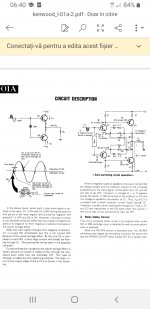
I think you gave up too soon on CFP because you might have not known the Kenwood l-01A .As this amp was made in 1980 and has a real incarnation that might easily drive nuts many of today's designers I'd say it's worth giving it a try because on 2 ohms loads seem to have the best response out of all topologies I ever tried at such low bias currents.Download the manual and see for yourself because their trick is minimal yet very effective and their output diode also allow for that hiperbolic class B bias while the parallel rc network really speeds up things at high frequency at least in simulation.
https://www.diyaudio.com/community/...nner-to-advanced.260627/page-164#post-7002643
I also think that somewhere along this topic @OldDIY suggested you constant current sourcing the bias current to prevent gm doubling in normal 2...3ef output stages , smth like in arcam diva p85...but Kenwood's idea looks pretty neat honestly and even the real thing had outstanding low thd for its time just that it used quite high speed devices. http://www.thevintageknob.org/kenwood-L-01A.html
Attachments
Just a couple comments.
The problems in the semiconductor market were a long time coming, additional COVID and related disasters only made things worse, but everything will be sorted in time. This does not affect design of any electronic circuits, so we can ignore that aspect.
Looking at these circuits in isolation can provide insight, but the fact remains that the output stage operates in a feedback loop (except stasis designs) and drives a reactive load. It has been shown that the load can affect the voltage amp stage, some designs more so than others. So the ultimate performance will depend on the entire circuit and the interaction between sections. There are many examples of excellent CFP amplifier designs (and signal amplifiers). Physical construction also matters a great deal.
One thing I applaud is that this has been a physical examination, along with those pitfalls, but there are so many variables that simulator drivers don't approach the real world conditions. I have learned a lot, and had many things I learned myself confirmed. That's always a massive help. But I want to caution people starting out that these are systems that operate together. You can't pick "the best of" and stich them together so you have "the best configuration". Finally, your PCB layout coupled with physical wiring will also have a huge effect on the performance of any signal amplifier, power amplifiers even more. So try to bear these things in mind.
-Chris

That's very true, Chris. Large signal behaviour, local oscillations, PCB track impedances and crosstalk - LTSpice or MC would not give reliable answers to us. Maybe there are professional SW solutions, at astronomic price I would guess.One thing I applaud is that this has been a physical examination, along with those pitfalls, but there are so many variables that simulator drivers don't approach the real world conditions.
If a circuit doesn't behaves well on resistive loads do you expect to behave better on reactive ones?
Sorry for the absence, personal stuff.@peufeu: We miss you! 🙂
There will be a season two, I'm working on it.
Parts ordered!
I have tons of stuff to do in August, so I guess September would be a nice date for season 2 😀
I have tons of stuff to do in August, so I guess September would be a nice date for season 2 😀
Looking forward to it!
I guess you have a concept you're about to build, or is it further testing you are preparing for?
I guess you have a concept you're about to build, or is it further testing you are preparing for?
The winner of the previous round was Class AB EF2 without emitter resistors, with bias current on the warm side (>50mA), fast drivers and fast output transistors. However bias stability was a problem (do you remember the diodes soldered on collector tab? lol).
So the configuration for this next board is one pair of BJTs, with one pair of MOSFETs as bootstrap cascodes. You can see the pads for the transistors at the top. The previous board didn't have cascodes. I tried it anyway. It worked very well, with the added bonus of much lower distortion due to constant Vce, which cancels the nonlinear input capacitance of the big BJTs. But it was a mess, using 9V batteries for biasing the gates, with wires and sticky tape holding together. The board looks like a warzone, with the pads beginning to pop off, so it was time to retire it.
At low Vce, the BJTs sweat a lot less, which means less trouble with self-heating and bias too. And it's cheaper to dissipate power in MOSFETs than to do it in BJTs, the safe operating area of the MOSFETs is larger, which means no need for another pair of BJTs to expand safe operating area. More devices means more capacitance, and I'd like to avoid that. Besides, my speakers are 92dB/1W so I don't need a monster amp. I've ordered some FDA38N30/FQA36P15 for cascodes, the safe operating area and thermal resistance are ridiculous on these devices.
Anyway.
First I plan to test a new type of driver arrangement that 1) really keeps the bias voltage between the two transistor bases constant, without influence from the driver Vbe, and 2) makes both drivers drive both output transistors so mismatch between drivers becomes irrelevant. Both driver transistors should share the base currents of both transistors almost equally. So I put the driver on a plug-in, which is really what I should have done last time.
Now for the bias. Since the diodes are still soldered on the Sankens, I will first try that, but I made a PCB for the bias control circuit, so hopefully it will stop breaking all the time. But I don't like this solution, because the flimsy wires to the diodes just want to break. And if the wires are robust, they just suck the heat out and it doesn't work. There's also the Thermaltrak MJLs, but I like the SanKens better, they're faster, and the temperature sensor in the thermaltraks is not placed where it should be for a fast response.
So I'm gonna try to set the bias using a thermal model. I previously measured the transient thermal impedance of these BJTs under heating. The response is easy enough to emulate with two resistors and two caps. If this RC network receives a current that is proportional to power dissipated in the transistor, it outputs what its Vbe should be due to self-heating. And since they'll operate at constant Vce, power is proportional to current, which avoids a multiplier. So all I have to do is sense the current (in the collector, since there are no emitter resistors), feed that into a RC network with proper values, and use the result to tweak the bias voltage. This calculation only gives heating relative to the heat sink temperature, so there will be a transistor to sense the heat sink. It works just fine in simulation, the circuit is not too complicated (two 50 cents opamps, a bunch of BJTs...) so that's what I'm gonna try.
I also want to check if I can use an analog multiplier to compute dissipated power (Vds*Id) in the MOSFETs to make a SOA protection circuit. That also works in simulation, and the multiplier is just a differential pair, it's not very accurate, but accurate enough for a protection circuit.
Next, perhaps you have noticed the QFN in the top right corner? I mean who would be crazy enough to bootstrap a TPA6120 and use it as predriver with "local" feedback?...
Thank you for the recap on 'season 1', and I'm looking forward too 'season 2' 🙂
I like your un-compromising approach, even if the complexity scares me a bit. To me it's certainly the most interesting and at the same time educating amp-project on the forum! I'm looking forward to the finale 🙂
On the local feedback side I have some new experiences thanks to Hugh/AKSA and his Alpha Nirvana amp that I built (and many kind emails from Hugh). Local feedback via RC from VAS to IPS to tune the global feedback vs frequency, and by doing so, also the output impedance vs frequency. I have tried his approach on a number of amps, tuning and simulating, and liked the results. It's a bit controversial, but I found it actually works for me and my ears. All credits to Hugh on that one!
On that subject, I also found that on commercial amps with not so much loop gain, simulating the complete amp with PS (using small PS caps as in commercial amps), the output impedance of the amp starts to increase in the low bass. I believe this is significant to the amps ability to control the woofer and give 'tight bass'.
Inspired by Hugh, and increasing (global) loop gain in the bass improves this, while the local/nested feedback is keeping the global loop gain on the low side in the rest of the band and preserves the 'sonic character' of the amp. Example: https://www.diyaudio.com/community/threads/hk-670-integrated-amp-sim-mods-etc.384245/
Good thing you haven't seen the software! lolthe complexity scares me a bit.
Thanks for the praise 😉
Interesting thread and findings... Did you find out why the output impedance increased with the small supply caps?
Happy not to see the software, it would only make my hair turn (more) gray! 🙂
As I see it, the impedance of the supply caps increases at LF, so the amps 'sees' a higher impedance from the supply, and the impedance curve of the PS caps is reflected on the output impedance. A lot of global feedback minimizes this (keeps output impedance extremely low), but with amps that has lower levels of feedback, output impedance is generally higher, and the increase at LF makes the bass sound sloppy. I have increased capacitance in the PS on amps many times in the past, and many times I found improvements in the bass, but it's an expensive way of doing it, and end results are not always satisfying.
I have not actually measured the output impedance of the amps, only simulated it, because simulation seems to agree with what I'm hearing.
The really subjective stuff is me liking the general sound of amps with less global feedback, but more in the bass to keep it tight. I seem to like sloppy mids and treble but not bass.. 🙂
The same for me Rallyfinnen  , the teaser in post #510 was not experienced as a teaser for me.
However, I'm really looking forward on the results of this ground breaking research of peufeu. I read he still likes the Sankens ( which I donated 2 pairs of).
I secretly hope for some more info on EF2 with Fet drivers and EF1 versus EF2. 🤞
, the teaser in post #510 was not experienced as a teaser for me.However, I'm really looking forward on the results of this ground breaking research of peufeu. I read he still likes the Sankens ( which I donated 2 pairs of).
I secretly hope for some more info on EF2 with Fet drivers and EF1 versus EF2. 🤞
Hmmm, I've run a few sims and didn't notice an increase in output impedance (in AC mode). So I did another sim injecting a 50Hz sine wave current into the output (with input grounded) to get the linearity of the output impedance, and then in this case, the supply cap made a difference. I have no idea why. With the output stage alone, it makes no difference, so it must be an interaction with the rest of the amp. But I don't like these sims because they don't have the 100Hz rectifier pulses. I mean if a bass note is played, the power supply will have a 100Hz ripple plus the ripple from that bass note, so it will also have many complex beat frequencies. It's a can of worms...I have not actually measured the output impedance of the amps, only simulated it, because simulation seems to agree with what I'm hearing.
Thanks for the transistors!I secretly hope for some more info on EF2 with Fet drivers and EF1 versus EF2. 🤞
EF1, you mean no drivers? at all?
Problem with FET drivers is they get very slow at low Vds so that would need an extra power supply with higher voltage. And they have low transconductance, so it's like the power transistors have a base resistor, and that's like having emitter resistors (Re is like Rb divided by hFe) and I don't want emitter resistors 😉
Oh, okay! You mean this one from Self?

EF I is like the Darlingtons that I tested earlier. From what I remember of the results, when the large transistor turns off, its driver is still attempting to drive the output through its emitter resistor, so the hFe of that half of the output stage drops from the product of both transistors hFe to just the driver. I didn't like the resulting gm and input current.
EF I is like the Darlingtons that I tested earlier. From what I remember of the results, when the large transistor turns off, its driver is still attempting to drive the output through its emitter resistor, so the hFe of that half of the output stage drops from the product of both transistors hFe to just the driver. I didn't like the resulting gm and input current.
- Home
- Amplifiers
- Solid State
- Power amp OUTPUT STAGE measurements shootout