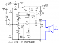
Calculate the RC timeconstant for two scenarios
(a) the 8 ohm loudspeaker load is disconnected, and output capacitor C2's only discharge path is bleeder resistor R7
(b) the 8 ohm loudspeaker load is connected, and output capacitor C2 is discharged by both R7 and the 8 ohm speaker, in parallel
_
(a) the 8 ohm loudspeaker load is disconnected, and output capacitor C2's only discharge path is bleeder resistor R7
(b) the 8 ohm loudspeaker load is connected, and output capacitor C2 is discharged by both R7 and the 8 ohm speaker, in parallel
_
Attachments


That doesn’t seem right to me. I have never heard any turn on or off thumps with my Almost Clone ACA mini. I think you might have an uncommon situation. What is your source? Maybe it has DC on the outputs?DC offset question.
On my unit (almost ACA clone board), when I turn the bias switch on, DC offset jumps to 5.6V and then slowly falls down to about 20mV over the next few minutes. When I turn the bias switch off, offset jumps again (to just over -5V) before again settling down over the next few minutes.
Are these jumps expected? If not, what should I look at? Thanks!
My amp is also an almost clone.
I've learned that the switch has to be off and the power supply lead removed before changing cables. It gets a minute or two to discharge after the power cord is disconnected, too.
Otherwise there are odd pops and noises. Might be the very sensitive speakers add to the effect but pulling the plug and waiting a bit is now standard operating procedure.
It doesn't take away from the amp. Love the thing.
What is your source? Maybe it has DC on the outputs?
Two different Schiit DACs, nothing, shorting plugs. Makes no difference - the offset always behaves this way.
That's a shame. 5V spike seems like a lot, and slowly dissipating, too. I don't know enough to say look one place or another.  Did you get the fairchild outputs? Any substitutions in your order deviating from the BOM?
Other more knowledgeable members could likely help you troubleshoot. This amp is art in simplicity and quality, it would be unfortunate to have to add a delay circuit to it.
Did you get the fairchild outputs? Any substitutions in your order deviating from the BOM?Other more knowledgeable members could likely help you troubleshoot. This amp is art in simplicity and quality, it would be unfortunate to have to add a delay circuit to it.
The outputs are Harris that Nelson donated. Substitutions from the BOM? Hmmm ...there may have been one or two but nothing significant - there's not much to the amp lol.Did you get the fairchild outputs? Any substitutions in your order deviating from the BOM?
Harris, right. Friday brain... 😀
Good point about the BOM.
I have an external speaker switch I've used for projects I knew were offset bombs for power on and off transients.
The P089ZB is your only known variable to me. I have some of those but don't use one with my ACA Mini. That may be the culprit. Did you use the amp without it at all?
I guess I'm just lucky, or maybe because I always have the SMPS plugged in and powered up I don't get the thumps. No harm. I'm always very happy with the amp. It powers my bedroom open baffle speakers wonderfully.
Check your PM, make sure RL4 and RR4 are each 6800 ohm and RL7 and RR7 are 1000 ohm. Check for cold joint.
With the slow rise via the 6K8 you shouldn’t have such thump.
Keep us posted.
With the slow rise via the 6K8 you shouldn’t have such thump.
Keep us posted.
RL4 measures 6.59K, RR4 is 6.7K.
RL7 is 1.008K, RR7 is 9.98K.
I'll start checking solder joints when I get a chance this w/e.
Thanks for the help 🙂
RL7 is 1.008K, RR7 is 9.98K.
I'll start checking solder joints when I get a chance this w/e.
Thanks for the help 🙂
RR7 is 998 or 9.98k? That's the bleeder resistor put there to prevent thumps. Close to 9.98K is too high. Maybe that's the problem.RL4 measures 6.59K, RR4 is 6.7K.
RL7 is 1.008K, RR7 is 9.98K.
I'll start checking solder joints when I get a chance this w/e.
Thanks for the help 🙂
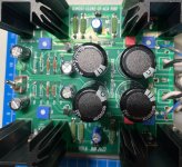
Yup, they're 1000uF. I looked over the solder joints and see nothing questionable - and since the behavior is the same on both channels it's unlikely the exact same bad solder was done twice. But I dunno, maybe I'm missing something?Please check CL5, CR5 they should each be 1000uF, are they on your pcb and well soldered ?
Attachments
Thanks for the pictures
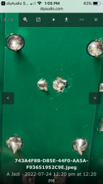
Check the solders for R7, these one in the middle are for RL7 and RR7 and kinda look odd. It might not be that since the issue is on both channels but it’s worth trying. Redo the solder then verify with a multimeter that each RL7 and RR7 make contact to ground
Check the solders for R7, these one in the middle are for RL7 and RR7 and kinda look odd. It might not be that since the issue is on both channels but it’s worth trying. Redo the solder then verify with a multimeter that each RL7 and RR7 make contact to ground
Attachments
- Home
- Amplifiers
- Pass Labs
- DIY ACA mini