You mean its legless 😀one of the pins snapped when i was messing around with it
The drilling looks good so it will look neat 👍
It worked out well. I'll try the LED tomorrow and start working on the front lettering, thats the biggest challengeYou mean its legless 😀
The drilling looks good so it will look neat 👍
Sounds like a plan. Lettering might not be easy. I think the days of Letraset and biscuit tin amplifiers are long gone although surprisingly I see Letraset is still round.
I've never heard of those tbh. So you design and print them yourself at home 🥦 oops that's what a typo get you LOL. Should be 😎
So think of the ones you put on model aircraft you print them, the cure them with spray that protects them, then soak them and slide them off to the surface and leave them to dry
Yes simlar, but once printed you spray with a sealant and leave to cure. Not used before so I'll try various colours before I do final one, so applying will be during the week sometime. I will post the trials though. I'm looking forward to seeing what they look like, if they do and it all works out OK I may offer it to people as a modification, at a cost of course
it's quite simple in fact, it has no mechanical resistance, chemically degrades and is not conductive enough.It was a separate concern from the OP's work and the PCB crack....
But you kind of leave the question open with that paragraph.
Why ? Does it deteriorate over time? and/or is not a good driver? Just give me a reason, a reason that explains why you don't use it, I wouldn't want to dirty the OP's thread, nor open a new thread about "how to repair PCB traces", there must already be many. Just tell me that. Thanks.
On the other hand, in some cases, it may be the only way to repair a very small track or even one that cannot be welded (I repaired a layer of a laser block with this)(I don't know the technical name in English)
We used to call those 'flexiprints'don't know the technical name in English
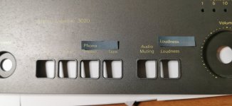
Font and colour look spot on. You could always put the soft clip LED on the front panel (seeing as you are good at drilling holes 😉)So I think we have the text font and colour about right. At the moment just print on a dark background but the final will be on transparent, which I'll try on an old panel first

Oh that's what I intend to do, just haven't decided where yet. Proberbly text in line with power led text with the led in line, but not next to the power leds'sWe used to call those 'flexiprints'
Font and colour look spot on. You could always put the soft clip LED on the front panel (seeing as you are good at drilling holes 😉)
That should work visually. You will find you can get creative when you diy stuff 😉 things like using a bicolour (red/green) LED so red for on and green for off. Maybe one for another day 🙂
Well the 3130 incorporates this I think. It has 3 legged LEDs and I think goes from yellow to red if it goes into soft clip mode, I think anyway
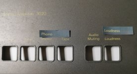
Back to the drawing board with the letters as you cant see them when applied and you can see the background filmThat should work visually. You will find you can get creative when you diy stuff 😉 things like using a bicolour (red/green) LED so red for on and green for off. Maybe one for another day 🙂
Oh heck. Lettering always has been a big problem for diy stuff. Transfers can work but they can be fragile unless coated over. This is something I made back in the 90's using rub on lettering. Even when coated with lacquer its still not exactly 'tough'.Back to the drawing board with the letters as you cant see them when applied and you can see the background film

so we may have a solution for the lettering and i will know on wedensday! so watch this space
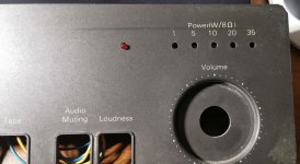
progress today, not a great deal, tried out the location for the LED and drilled an old cover so i think i can get that to work ok.
The final version will have a slightly tighter drilling, the one i did today was a test(not sure what colour LED to have yet)
finished re-capping all 3 boards, so thats done and replaced a couple of transistors with originals that had 'alternatives fitted'(and not very well) and started cleaning the main board, that has loads of glue on it.
so if i can get the lettering done ok, as the trial print works and ive nailed the font and the colour, then it should all be good.
Ive decided to mount the op amp (new UA741's and bases coming tomorrow) on a base so if for some reason it failed it can be replaced, the base can then be secured without me having to worry about getting glue all over the pins when i fill the holes in
For that i will fit some waxed shrik tube over the terminals so they will remove easily after filling the wholes
Attachments
Right then 🙂so we may have a solution for the lettering and i will know on wedensday! so watch this space
741's have a different pin out to the others because they are a single opamp and not a dual. Pins 2, 3 and 4 are the same but the output is on pin 6 and the positive supply is on pin 7.Ive decided to mount the op amp (new UA741's and bases coming tomorrow) on a base so if for some reason it failed it can be replaced, the base can then be secured without me having to worry about getting glue all over the pins when i fill the holes in
I don't know how bad or good he can be as a conductiver. To be frank, I haven't measured it. Perhaps it depends on the binder and the amount of silver, that is, on the quality of the product. What I can assure you is that for those damaged parts - such as the curved tracks that end in the "holes" of the TR -, with a good hand and applying several layers, it was a quick and effective solution for me when I used it.it's quite simple in fact, it has no mechanical resistance, chemically degrades and is not conductive enough.
On the other hand, in some cases, it may be the only way to repair a very small track or even one that cannot be welded (I repaired a layer of a laser block with this)(I don't know the technical name in English)
View attachment 1072498
Using it for the terminals of a flex is a good idea. I knew I was going to learn something new.
Thanks for answering.
Last edited:
- Home
- Amplifiers
- Solid State
- NAD 3020 project, strip down and upgrade.