Try this ECC85 Philips model:
Code:
**** ECC85 ** Advanced Grid Current **********************************
* Created on 07/03/2022 10:00 using paint_kit.jar 3.1
* www.dmitrynizh.com/tubeparams_image.htm
* Plate Curves image file: ecc85.png
* Data source link:
*----------------------------------------------------------------------------------
.SUBCKT ECC85 1 2 3 ; Plate Grid Cathode
+ PARAMS: CCG=3P  CGP=1.5P CCP=0.18P
+ MU=65.79 KG1=631.27 KP=222.14 KVB=732.25 VCT=0.5788 EX=1.472
+ VGOFF=-0.6 IGA=4.7E-4 IGB=0.171 IGC=9.12 IGEX=1.54
* Vp_MAX=375 Ip_MAX=25 Vg_step=1 Vg_start=0 Vg_count=11
* Rp=4000 Vg_ac=55 P_max=2.5 Vg_qui=-48 Vp_qui=300
* X_MIN=33 Y_MIN=35 X_SIZE=802 Y_SIZE=541 FSZ_X=1296 FSZ_Y=736 XYGrid=true
* showLoadLine=n showIp=y isDHT=n isPP=n isAsymPP=n showDissipLimit=y
* showIg1=y gridLevel2=y isInputSnapped=n
* XYProjections=n harmonicPlot=n dissipPlot=n
*----------------------------------------------------------------------------------
E1 7 0 VALUE={V(1,3)/KP*LOG(1+EXP(KP*(1/MU+(VCT+V(2,3))/SQRT(KVB+V(1,3)*V(1,3)))))}
RE1 7 0 1G  ; TO AVOID FLOATING NODES
G1 1 3 VALUE={(PWR(V(7),EX)+PWRS(V(7),EX))/KG1}
RCP 1 3 1G   ; TO AVOID FLOATING NODES
C1 2 3 {CCG} ; CATHODE-GRID
C2 2 1 {CGP} ; GRID=PLATE
C3 1 3 {CCP} ; CATHODE-PLATE
RE2 2 0 1G
EGC 8 0 VALUE={V(2,3)-VGOFF} ; POSITIVE GRID THRESHOLD
GG 2 3 VALUE={(IGA+IGB/(IGC+V(1,3)))*(MU/KG1)*(PWR(V(8),IGEX)+PWRS(V(8),IGEX))}
.ENDS
*$
Attachments
Hi ....Great !
Thanks Thanks for the ECC85 Modell Alot Koonw .😉Good Modell works well .....
Gruss Chris
Thanks Thanks for the ECC85 Modell Alot Koonw .😉Good Modell works well .....
Gruss Chris
Hi all
A further model of mine. This time the 19EZ8, one of the very rare triple triodes.
This triode was quite tricky to fit, because the plate resistance shows a certain drop when a larger grid current is present.
However, this is not of relevance for most applications.
Have fun! 🙂
BR Adrian
A further model of mine. This time the 19EZ8, one of the very rare triple triodes.
This triode was quite tricky to fit, because the plate resistance shows a certain drop when a larger grid current is present.
However, this is not of relevance for most applications.
Have fun! 🙂
BR Adrian
Code:
*19EZ8 LTspice model based on the generic triode model from Adrian Immler, version i5
*A version log is at the end of this file
*100h BurnIn of 4 tubes, sample selection and measurements done in June 2022
*Params fitted to the measured values by Adrian Immler, July 2022
*The high fit quality is presented at adrianimmler.simplesite.com
*History's best of tube describing art (plus some new ideas) is merged to this new approach.
*@ neg. Vg, Ia accuracy is similar to Koren models, and unrivaled for remote cutoff triodes
*@ small neg. Vg, the "Anlauf" current is considered.
*@ pos. Vg, Ig and Ia accuracy is on an unrivaled level (including neg. Va range!)
*This offers new simulation possibilities like grid resistor bias, backward plate modulated stages,
*Audion radio circuits, low voltage amps, guitar distortion stages or pulsed stages.
*             Westinghouse
*             |    anode (plate)
*             |    | grid
*             |    | | cathode
*             |    | | |
.subckt 19EZ8.WHi5 A G K
+ params:
*Parameters for space charge current Is (100% assigned to Ia @ Vg < 0)
+ mu   = 95    ;Determines the voltage gain @ constant Ia
+ rad  = 10k9  ;Differential anode resistance, set @ Iad and Vg=0V
+ Vct  = 0.25  ;Offsets the Ia-traces on the Va axis. Electrode material's contact potential
+ kp   = 160   ;Mimics the island effect
+ xs   = 1.5   ;Determines the curve of the Ia traces. Typically between 1.2 and 1.8
+ kIsr = 45m   ;Va-independent part of the Is reduction when grid current occurs
+ kvdg  = 90   ;Va-dependent part of the Is reduction when grid current occurs
*
*Parameters for assigning the space charge current to Ia and Ig @ Vg > 0
+ kB   = 0.25  ;Describes how fast Ia drops to zero when Va approaches zero.
+ radl = 100   ;Differential resistance for the Ia emission limit @ very small Va and Vg > 0
+ tsh  = 8     ;Ia transmission sharpness from 1st to 2nd Ia area. Keep between 3 and 20. Start with 20.
+ xl   = 1.6   ;Exponent for the emission limit
*
*Parameters of the grid-cathode vacuum diode
+ kg = 480     ;Inverse scaling factor for the Va independent part of Ig (caution - interacts with xg!)
+ Vctg = -0.22 ;Offsets the log Ig-traces on the Vg axis. Electrode material's contact potential
+ xg   = 1.4   ;Determines the curve of the Ig slope versus (positive) Vg and Va >> 0
+ VT   = 0.112 ;Log(Ig) slope @ Vg<0. VT=k/q*Tk (cathodes absolute temp, typically 1150K)
+ rTr  = 0.7   ;ratio of VT for Igr. Typically 0.8
+ kVT= -5m     ;Va dependent koeff. of VT
+ gft1 = 0.05  ;reduces the steering voltage around Vg=-Vg0, for finetuning purposes
+ gft1a= 0.15  ;reduces the steering voltage around Vg=-Vg0. Effect decreases with 1/(1+kB*Va)
+ gft2 = 0.23  ;finetunes the Igr drop @ increasing Va and around Vg=-Vg0
*
*Parameters for the caps
+ cag  = 1p5   ;From Tung-Sol datasheet
+ cak  = 0p4   ;From Tung-Sol datasheet
+ cgk  = 2p4   ;From Tung-Sol datasheet
*
*special purpose parameters
+ os = 1       ;Overall scaling factor, if a user wishes to simulate manufacturing tolerances
+ murc = 10    ;Mu of the remote cutoff triode
+ ksrc = 1G    ;Inverse Iarc gain factor for the remote cutoff triode
+ kprc = 55    ;Mimics the island effect for the remote cutoff triode
+ Vbatt = 0    ;heater battery voltage for direct heated battery triodes
+ Vdrmax = 100 ;max voltage of internal Vg drop, for convergence improvements
*
*Calculated parameters
+ Iad = {100/rad} ;Ia where the anode a.c. resistance is set according to rad.
+ ks = {pow(mu/(rad*xs*Iad**(1-1/xs)),-xs)} ;Reduces the unwished xs influence to the Ia slope
+ ksnom = {pow(mu/(rad*1.5*Iad**(1-1/1.5)),-1.5)} ;Sub-equation for calculating Vg0
+ Vg0 = {Vct + (Iad*ks)**(1/xs) - (Iad*ksnom)**(2/3)} ;Reduces the xs influence to Vct.
+ kl = {pow(1/(radl*xl*Ild**(1-1/xl)),-xl)} ;Reduces the xl influence to the Ia slope @ small Va
+ Ild = {sqrt(radl)*1m} ;Current where the Il a.c. resistance is set according to radl.
*
*Space charge current model
Rak A K 100G ;avoids "floating net" errors
Bft   ft 0 V=1/(1+pow(2*abs(v(G,Ki)+Vg0),3)) ;an auxiliary voltage to finetune the triode around Vg=-Vg0
Bggi GGi 0 V=(v(Gi,Ki)+Vg0)*(1/(1+kIsr*max(0, v(G,Ki)+Vg0))) - gft1*v(ft) - gft1a*v(ft)/(1+kB*v(Ahc)) ;Effective internal grid voltage.
Bahc Ahc 0 V=uramp(v(A,Ki)) ;Anode voltage, hard cut to zero @ neg. value
Bst   St 0 V=uramp(max(v(GGi)+v(A,Ki)/(mu), v(A,Ki)/kp*ln(1+exp(kp*(1/mu+v(GGi)/(1+v(Ahc)))))));Steering volt.
Bs    Ai Ki I=os/ks*pow(v(St),xs) ;Langmuir-Childs law for the space charge current Is
*Bstrc Strc 0 V=uramp(max(v(GGi)+v(Ahc)/(murc), v(Ahc)/kprc*ln(1+exp(kprc*(1/murc+v(GGi)/(1+v(Ahc)))))));FOR REMOTE CUTOFF TUBES ONLY
*Bsrc   Ai Ki I=os/ksrc*pow(v(Strc),xs) ;FOR REMOTE CUTOFF TUBES ONLY
*
*Anode current limit @ small Va
.func smin(z,y,k) {pow(pow(z+1f, -k)+pow(y+1f, -k), -1/k)} ;Min-function with smooth trans.
.func ssmin(z,y,k) {min(min(z,y), smin(z*1.003,y*1.003,k))};smin-function which suppresses small residual differences
Ra  A Ai 1
Bgl Gi A I=uramp(i(Ra)-ssmin(1/kl*pow(v(Ahc),xl),i(Ra),tsh)) ;Ia emission limit
*
*Grid model
Rgk G K 10G ;avoids "floating net" errors
Bvdg G Gi I=1/kvdg*pow(v(G,Gi),1.5) ;Reduces the internal effective grid voltage when Ig rises
Bcoh G Gi I=pow(uramp(v(G,Gi)-Vdrmax),2) ;A convergence help which softly limits the internal Vg voltage drop.
Rgip G Gi 1G ;avoids some warnings
.func fVT() {VT*exp(-kVT*sqrt(v(A,Ki)))}
.func Ivd(Vvd, kvd, xvd, VTvd)  {if(Vvd < 3, 1/kvd*pow(VTvd*xvd*ln(1+exp(Vvd/VTvd/xvd)),xvd), 1/kvd*pow(Vvd, xvd))} ;Vacuum diode function
Bgvd G Ki I=Ivd(v(G,Ki) + Vctg + min(0,v(A,Ki)/mu), kg/os, xg, fVT()) ;limits the internal Vg for convergence reasons
Bstn Stn 0 V=v(GGi)+min(0,v(A,Ki))/mu ;special steering voltage, sensitive to negative Anode voltages only
Bgr Gi Ai I= ivd(v(Stn),ks/os, xs, rTr*fVT())/(1+(kB+v(ft)*gft2)*v(Ahc));Is reflection to grid when Va approaches zero
*Bgr Gi Ai I=(ivd(v(Stn),ks/os, xs, rTr*fVT())+os/ksrc*pow(v(GGi),xs))/(1+(kB+v(ft)*gft2)*v(Ahc));FOR REMOTE CUTOFF TUBES ONLY
Bs0 Ai Ki  I=uramp(ivd(v(Stn),ks/os, xs, rTr*fVT()) - os/ks*pow(v(Stn),xs))
Bbatt Ki K V=Vbatt/2 ;for battery heated triodes; Offsets the average cathode potential to the half heater battery voltage
*
*Caps
C1 A G {cag}
C2 A K {cak}
C3 G K {cgk}
.ends
*
*Version log
*i1 :Initial version
*i2 :Pin order changed to the more common order A G K (Thanks to Markus Gyger for his tip)
*i3 :bugfix of the Ivd-function: now also usable for larger Vvd
*i4: Rgi replaced by a virtual vacuum diode (better convergence). ft1 deleted (no longer needed)
;2 new params for Ig finetuning @ Va and Vg near zero. New overall scaling factor os for aging etc.
*i5: improved convergence performance. PosVg/NegVa area now correct. Also accurate now for remote cutoff triodes!
Attachments

Well, here comes a hope and a prayer. I'm hoping someone knows of a good LTspice pentode model for 6JC6A or 6JD6. These are frame grid pentodes.
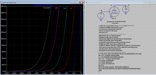
Try this 6JC6-A GE model:
Code:
**** 6JC6_A ******************************************
* Created on 07/12/2022 15:45 using paint_kip.jar
* www.dmitrynizh.com/tubeparams_image.htm
* Plate Curves image file: 6jc6-a.png
* Data source link: <plate curves URL>
*----------------------------------------------------------------------------------
.SUBCKT 6JC6_A P G2 G K ; LTSpice tetrode.asy pinout
* .SUBCKT 6JC6_A P G K G2 ; Koren Pentode Pspice pinout
+ PARAMS: MU=57.08 KG1=212.97 KP=404.37 KVB=86.36 VCT=-0.2559 EX=1.092 KG2=203.74 KNEE=3502.28 KVC=1.863
+ KLAM=2.504E-11 KLAMG=1.709E-4  KD=115.04 KC=1.191E-4 KR1=3.83E-5 KR2=0.0199 KVBG=4.18E-4 KB1=5.114 KB2=1.333 KB3=1.075 KB4=0.2418 KVBGI=1.645E-4 KNK=0.132 KNG=2.17E-5 KNPL=0.02082 KNSL=4.121E-4 KNPR=0.2031 KNSR=85.51
+ CCG=8.5P CGP=0.019P CCP=3P VGOFF=-0.6 IGA=0.00106 IGB=0.12 IGC=9.84 IGEX=1.74
* Vp_MAX=500 Ip_MAX=35 Vg_step=1 Vg_start=0 Vg_count=12
* X_MIN=56 Y_MIN=36 X_SIZE=774 Y_SIZE=538 FSZ_X=1296 FSZ_Y=736 XYGrid=false
* Rp=1400 Vg_ac=20 P_max=3.1 Vg_qui=-5.5 Vp_qui=300
* showLoadLine=n showIp=y isDHP=n isPP=n isAsymPP=n isUL=n showDissipLimit=y
* showIg1=y isInputSnapped=y addLocalNFB=n
* XYProjections=n harmonicPlot=y dissipPlot=n
* UL=0.43 EG2=125 gridLevel2=y addKink=y isTanhKnee=n advSigmoid=y
*----------------------------------------------------------------------------------
RE1  7 0  1G    ; DUMMY SO NODE 7 HAS 2 CONNECTIONS
E1   7 0  VALUE=  ; E1 BREAKS UP LONG EQUATION FOR G1.
+{V(G2,K)/KP*LOG(1+EXP((1/MU+(VCT+V(G,K))/SQRT(KVB+V(G2,K)*V(G2,K)))*KP))}
RE2  6 0  1G    ; DUMMY SO NODE 6 HAS 2 CONNECTIONS
E2  6 0  VALUE={(PWR(V(7),EX)+PWRS(V(7),EX))} ; Kg1 times KIT current
E4   8 0  VALUE={V(P,K)/KNEE/(KVBGI+V(6)*KVBG)}
E5  81 0  VALUE={PWR(V(8),KB1)}
E6  82 0  VALUE={PWR(V(8),KB2)}
E7  83 0  VALUE={PWR(V(8),KB3)}
E8   9 0  VALUE={PWR(1-EXP(-V(81)*(KC+KR1*V(82))/(KD+KR2*V(83))),KB4)*1.5708}
RE4  8 0  1
RE5 81 0  1
RE6 82 0  1
RE7 83 0  1
RE8  9 0  1
RE21 21 0 1
E21  21 0 VALUE={V(6)/KG1*V(9)} ; Ip with knee but no slope and no kink
RE22 22 0 1 ; E22: kink curr deviation for plate
E22  22 0 VALUE={V(21)*LIMIT(KNK-V(G,K)*KNG,0,0.3)*(-ATAN((V(P,K)-KNPL)/KNSL)+ATAN((V(P,K)-KNPR)/KNSR))}
G1   P K  VALUE={V(21)*(1+KLAMG*V(P,K))+KLAM*V(P,K) + V(22)}
G2   G2 K  VALUE={V(6)/KG2*(KVC-V(9))/(1+KLAMG*V(P,K)) - V(22)}
RCP  P K  1G     ; FOR CONVERGENCE
C1   K G  {CCG}  ; CATHODE-GRID 1
C2   G P  {CGP}  ; GRID 1-PLATE
C3   K P  {CCP}  ; CATHODE-PLATE
RE23 G 0 1G
GG G K VALUE={(IGA+IGB/(IGC+V(P,K)))*(MU/KG1)*
+(PWR(V(G,K)-VGOFF,IGEX)+PWRS(V(G,K)-VGOFF,IGEX))}
.ENDS
*$
Attachments
Last edited:
Thanks so much!
I'm having a bit of trouble getting it to work with the DN2540 CCS, but it looks like that's my problem, not the model's.
I'm having a bit of trouble getting it to work with the DN2540 CCS, but it looks like that's my problem, not the model's.
Last edited:
Actually, I'm not able to get the 6JC6_A model to work in the circuit from post #1 of the thread about PP 6L6 using local parallel feedback (the DCPP circuit).
I replaced the CCS with a resistor in the LTP tail (5.1k for 10mA per 6JC6) and got it to run. But if I change any part value, even just the screen grid bypass cap value, it fails to converge. I'm not seeing that behavior from any of the other models I've tried (6EW6, 6CB6, 6AK5).
Any troubleshooting suggestions?
Last edited:
.option noopiter
.options GminSteps=0
.options SrcSteps=1000
You can try these options, as nearly all paint tool model having "Advance Knee" need these.
.options GminSteps=0
.options SrcSteps=1000
You can try these options, as nearly all paint tool model having "Advance Knee" need these.
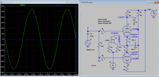
I try to sim the sch you mentioned, but I have trouble running it too, just the 1st stage. After I added one 47k screen resistor it's ok. Are you missing a screen resistor? Or current demanded by CCS can not be fulfilled.
Attachments
Last edited:
That second 47k resistor you added (R6 in your drawing), is in parallel with R5 (also 47k ohms), which simply reduces the value of R5 from 47k down to 23.5k ohms. That makes the 6JC6A plate voltage 99V, with the screen voltage way up at 231V. Is that a useful operating point for 6JC6A? I was aiming for somewhere around 150V to 180V on both the plate and screen of the 6CJ6A. Perhaps that's not what it needs.
I also tried reducing the values of the plate resistors to 22k and even 15k, and reducing the screen resistor to 39k and 33k. The sim still didn't run reliably. I will try adding the extra lines you mentioned in post 3349 this evening, after work.
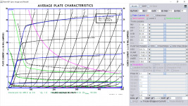
http://www.nj7p.org/Tubes/PDFs/Frank/135-GE/6JC6A.pdf
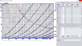
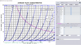
6JC6A load line for Rp = 22k, Ec2 = 125V and Ebb = 375V:


I also tried reducing the values of the plate resistors to 22k and even 15k, and reducing the screen resistor to 39k and 33k. The sim still didn't run reliably. I will try adding the extra lines you mentioned in post 3349 this evening, after work.
http://www.nj7p.org/Tubes/PDFs/Frank/135-GE/6JC6A.pdf
6JC6A load line for Rp = 22k, Ec2 = 125V and Ebb = 375V:
Here is better operating points: Since you predefined the constant current amount, the only variable option is to adjust the screen current, with 47k-56k screen resistor. The plate load is pretty much fixed as shown in the curve you attached. You'll need the "options", you don't want it to attempt the iterations it'll fail or gabble.
Attachments
Last edited:
I'm looking for some help. If this is not the place, can you please direct me to a site that might be able to help...
I have a question for anyone that may be able to help. I am in the midst of a second generation rebuild of a Dynaco PAS4 tube preamp. This is NOT a PAT model or an upgraded PAS 3. This was a very limited production preamp which I think was the last tube preamp that Dynaco produced. It was way overbuilt as far as power supply and sounds fantastic. Dissappears in the system.
My problem is that the 50Kohm stereo balance control (original) has developed noise and needs to be replaced. Tried cleaning it - no joy - lots of noise. It seems that there are two choices - cheap or unaffordable.
So my question is this: Can I use a good quality stereo volume control (linear) and just wire one channel in reverse of the other s on o that at center positon both channels have equal settings? Would I have to add any additional components?
I have read a lot of posts that say this should work fine as long as it is a linear (not logrithmic) volume control. However, no one has ever said they have actually tried it.
Any help would be greatly appreciated....all comments welcome!
Thanks in advance.
Hi, wonder if anyone has a good accurate model for either the russian 6N13s ie 6H13C or a 6AS7?
https://frank.pocnet.net/sheets/113/6/6N13S.pdf
https://frank.pocnet.net/sheets/093/6/6AS7GA.pdf
It's for simulating an OTL circuit. Probably going to operate the triode at around the quiescent point of Plate voltage~150V, Gate at ~ -70V and Iplate~45mA
https://frank.pocnet.net/sheets/113/6/6N13S.pdf
https://frank.pocnet.net/sheets/093/6/6AS7GA.pdf
It's for simulating an OTL circuit. Probably going to operate the triode at around the quiescent point of Plate voltage~150V, Gate at ~ -70V and Iplate~45mA
Hi, I was in a similar situation, looking for a dual log pot for my dynaco SCA35. Here's a possible solution:I'm looking for some help. If this is not the place, can you please direct me to a site that might be able to help...
I have a question for anyone that may be able to help. I am in the midst of a second generation rebuild of a Dynaco PAS4 tube preamp. This is NOT a PAT model or an upgraded PAS 3. This was a very limited production preamp which I think was the last tube preamp that Dynaco produced. It was way overbuilt as far as power supply and sounds fantastic. Dissappears in the system.
My problem is that the 50Kohm stereo balance control (original) has developed noise and needs to be replaced. Tried cleaning it - no joy - lots of noise. It seems that there are two choices - cheap or unaffordable.
So my question is this: Can I use a good quality stereo volume control (linear) and just wire one channel in reverse of the other s on o that at center positon both channels have equal settings? Would I have to add any additional components?
I have read a lot of posts that say this should work fine as long as it is a linear (not logrithmic) volume control. However, no one has ever said they have actually tried it.
Any help would be greatly appreciated....all comments welcome!
Thanks in advance.
(1) https://www.ebay.com/itm/283424937478?hash=item41fd715606:g:688AAOSwfuddNMWG
1st one is an example of a stepped pot, just put in the correct resistor values and it will be precise and will never develop any scratchiness. There are no carbon tracks to wear out. This one is a 24 step for volume, For balance control, better to use a 23 step control so that way the middle of the pot is the perfect balance.
Nick
Here is better operating points: Since you predefined the constant current amount, the only variable option is to adjust the screen current, with 47k-56k screen resistor. The plate load is pretty much fixed as shown in the curve you attached. You'll need the "options", you don't want it to attempt the iterations it'll fail or gabble.
Hi Koonw, and thank you for helping. I tried the new directives and parts values and it all works perfectly. If this is indicative of what to expect in real life, it looks like 6JC6A is one of the best pentodes to use in this way, along with 6EJ7 and possibly 12GN7A, I've got lots to think about here! Thanks again.
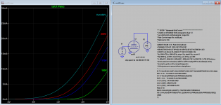
Try this 6AS7 GE model as requested:
Code:
**** 6AS7_GE ** Advanced Grid Current ***************Post*******************
* Created on 07/15/2022 14:58 using paint_kit.jar 3.1
* www.dmitrynizh.com/tubeparams_image.htm
* Plate Curves image file: 6as7-ge.png
* Data source link:
*----------------------------------------------------------------------------------
.SUBCKT 6AS7_GE 1 2 3 ; Plate Grid Cathode
+ PARAMS: CCG=8P  CGP=11P CCP=3P
+ MU=2.476 KG1=8988.67 KP=7.069 KVB=159.84 VCT=8.876 EX=2.023
+ VGOFF=-0.6 IGA=0.001 IGB=0.3 IGC=8 IGEX=2
* Vp_MAX=280 Ip_MAX=200 Vg_step=20 Vg_start=0 Vg_count=10
* Rp=4000 Vg_ac=55 P_max=13 Vg_qui=-48 Vp_qui=300
* X_MIN=70 Y_MIN=59 X_SIZE=797 Y_SIZE=570 FSZ_X=1296 FSZ_Y=736 XYGrid=false
* showLoadLine=n showIp=y isDHT=n isPP=n isAsymPP=n showDissipLimit=y
* showIg1=y gridLevel2=y isInputSnapped=n
* XYProjections=n harmonicPlot=n dissipPlot=n
*----------------------------------------------------------------------------------
E1 7 0 VALUE={V(1,3)/KP*LOG(1+EXP(KP*(1/MU+(VCT+V(2,3))/SQRT(KVB+V(1,3)*V(1,3)))))}
RE1 7 0 1G  ; TO AVOID FLOATING NODES
G1 1 3 VALUE={(PWR(V(7),EX)+PWRS(V(7),EX))/KG1}
RCP 1 3 1G   ; TO AVOID FLOATING NODES
C1 2 3 {CCG} ; CATHODE-GRID
C2 2 1 {CGP} ; GRID=PLATE
C3 1 3 {CCP} ; CATHODE-PLATE
RE2 2 0 1G
EGC 8 0 VALUE={V(2,3)-VGOFF} ; POSITIVE GRID THRESHOLD
GG 2 3 VALUE={(IGA+IGB/(IGC+V(1,3)))*(MU/KG1)*(PWR(V(8),IGEX)+PWRS(V(8),IGEX))}
.ENDS
*$
Attachments
Last edited:
Thanks, that's great. Just what I am looking for.Try this 6AS7 GE model as requested:
Code:**** 6AS7_GE ** Advanced Grid Current ***************Post******************* * Created on 07/15/2022 14:58 using paint_kit.jar 3.1 * www.dmitrynizh.com/tubeparams_image.htm * Plate Curves image file: 6as7-ge.png * Data source link: *---------------------------------------------------------------------------------- .SUBCKT 6AS7_GE 1 2 3 ; Plate Grid Cathode + PARAMS: CCG=8P CGP=11P CCP=3P + MU=2.476 KG1=8988.67 KP=7.069 KVB=159.84 VCT=8.876 EX=2.023 + VGOFF=-0.6 IGA=0.001 IGB=0.3 IGC=8 IGEX=2 * Vp_MAX=280 Ip_MAX=200 Vg_step=20 Vg_start=0 Vg_count=10 * Rp=4000 Vg_ac=55 P_max=13 Vg_qui=-48 Vp_qui=300 * X_MIN=70 Y_MIN=59 X_SIZE=797 Y_SIZE=570 FSZ_X=1296 FSZ_Y=736 XYGrid=false * showLoadLine=n showIp=y isDHT=n isPP=n isAsymPP=n showDissipLimit=y * showIg1=y gridLevel2=y isInputSnapped=n * XYProjections=n harmonicPlot=n dissipPlot=n *---------------------------------------------------------------------------------- E1 7 0 VALUE={V(1,3)/KP*LOG(1+EXP(KP*(1/MU+(VCT+V(2,3))/SQRT(KVB+V(1,3)*V(1,3)))))} RE1 7 0 1G ; TO AVOID FLOATING NODES G1 1 3 VALUE={(PWR(V(7),EX)+PWRS(V(7),EX))/KG1} RCP 1 3 1G ; TO AVOID FLOATING NODES C1 2 3 {CCG} ; CATHODE-GRID C2 2 1 {CGP} ; GRID=PLATE C3 1 3 {CCP} ; CATHODE-PLATE RE2 2 0 1G EGC 8 0 VALUE={V(2,3)-VGOFF} ; POSITIVE GRID THRESHOLD GG 2 3 VALUE={(IGA+IGB/(IGC+V(1,3)))*(MU/KG1)*(PWR(V(8),IGEX)+PWRS(V(8),IGEX))} .ENDS *$
Hi, Here's another possible replacement...I'm looking for some help. If this is not the place, can you please direct me to a site that might be able to help...
I have a question for anyone that may be able to help. I am in the midst of a second generation rebuild of a Dynaco PAS4 tube preamp. This is NOT a PAT model or an upgraded PAS 3. This was a very limited production preamp which I think was the last tube preamp that Dynaco produced. It was way overbuilt as far as power supply and sounds fantastic. Dissappears in the system.
My problem is that the 50Kohm stereo balance control (original) has developed noise and needs to be replaced. Tried cleaning it - no joy - lots of noise. It seems that there are two choices - cheap or unaffordable.
So my question is this: Can I use a good quality stereo volume control (linear) and just wire one channel in reverse of the other s on o that at center positon both channels have equal settings? Would I have to add any additional components?
I have read a lot of posts that say this should work fine as long as it is a linear (not logrithmic) volume control. However, no one has ever said they have actually tried it.
Any help would be greatly appreciated....all comments welcome!
Thanks in advance.
https://www.ebay.com/itm/224095040608?hash=item342d1af460:g:mpwAAOSwHvVfHc9O
maybe you can look at the part number and see if you can get a better price elswhere
- Home
- Amplifiers
- Tubes / Valves
- Vacuum Tube SPICE Models