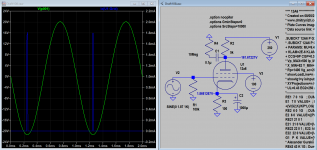
Have you read the sticky located here---> Recommended highly.How should I add THD measurements for several testpoint in a circuit with LTSpice ? Right now I can only simulate measuring voltages and (mili)amperes. The matching with my actual build is nearly perfect, so it’s time for some more advanced measurements.
Regards, Gerrit
Unfortunately, I think the model contains an error somewhere?Try this 12A6 RCA model:
Code:**** 12A6 ****************************************** * Created on 07/25/2022 13:58 using paint_kip.jar * www.dmitrynizh.com/tubeparams_image.htm * Plate Curves image file: 12a6.png * Data source link: <plate curves URL> *---------------------------------------------------------------------------------- .SUBCKT 12A6 P G2 G K ; LTSpice tetrode.asy pinout * .SUBCKT 12A6 P G K G2 ; Koren Pentode Pspice pinout + PARAMS: MU=9.4 KG1=6979.25 KP=110.52 KVB=339.16 VCT=2.657 EX=1.541 KG2=28485.35 KNEE=17.92 KVC=1.801 + KLAM=2E-6 KLAMG=6.204E-8 KNEE2=0.201 KNEX=0.05115 KNK=-0.04158 KNG=0.008585 KNPL=0.625 KNSL=22.22 KNPR=164.07 KNSR=73.58 + CCG=9P CGP=0.3P CCP=9P VGOFF=-1.8 IGA=1.786 IGB=9.5 IGC=0.716 IGEX=0.24 * Vp_MAX=500 Ip_MAX=160 Vg_step=10 Vg_start=20 Vg_count=13 * X_MIN=82 Y_MIN=29 X_SIZE=760 Y_SIZE=607 FSZ_X=1296 FSZ_Y=736 XYGrid=true * Rp=1400 Vg_ac=20 P_max=7.5 Vg_qui=-40 Vp_qui=300 * showLoadLine=n showIp=y isDHP=n isPP=n isAsymPP=n isUL=n showDissipLimit=y * showIg1=y isInputSnapped=y addLocalNFB=n * XYProjections=n harmonicPlot=y dissipPlot=n * UL=0.43 EG2=250 gridLevel2=y addKink=y isTanhKnee=y advSigmoid=n *---------------------------------------------------------------------------------- RE1 7 0 1G ; DUMMY SO NODE 7 HAS 2 CONNECTIONS E1 7 0 VALUE= ; E1 BREAKS UP LONG EQUATION FOR G1. +{V(G2,K)/KP*LOG(1+EXP((1/MU+(VCT+V(G,K))/SQRT(KVB+V(G2,K)*V(G2,K)))*KP))} RE2 6 0 1G ; DUMMY SO NODE 6 HAS 2 CONNECTIONS E2 6 0 VALUE={(PWR(V(7),EX)+PWRS(V(7),EX))} ; Kg1 times KIT current RE21 21 0 1 E21 21 0 VALUE={V(6)/KG1*ATAN((V(P,K)+KNEX)/KNEE)*TANH(V(P,K)/KNEE2)} ; Ip with knee but no slope and no kink RE22 22 0 1 ; E22: kink curr deviation for plate E22 22 0 VALUE={V(21)*LIMIT(KNK-V(G,K)*KNG,0,0.3)*(-ATAN((V(P,K)-KNPL)/KNSL)+ATAN((V(P,K)-KNPR)/KNSR))} G1 P K VALUE={V(21)*(1+KLAMG*V(P,K))+KLAM*V(P,K) + V(22)} * Alexander Gurskii screen current, see audioXpress 2/2011, with slope and kink added RE43 43 K 1G ; Dummy E43 43 G2 VALUE={0} ; Dummy G2 43 K VALUE={V(6)/KG2*(KVC-ATAN((V(P,K)+KNEX)/KNEE)*TANH(V(P,K)/KNEE2))/(1+KLAMG*V(P,K))-V(22)} RCP P K 1G ; FOR CONVERGENCE C1 K G {CCG} ; CATHODE-GRID 1 C2 G P {CGP} ; GRID 1-PLATE C3 K P {CCP} ; CATHODE-PLATE RE23 G 0 1G GG G K VALUE={(IGA+IGB/(IGC+V(P,K)))*(MU/KG1)* +(PWR(V(G,K)-VGOFF,IGEX)+PWRS(V(G,K)-VGOFF,IGEX))} .ENDS *$
It takes forever to simulate a transient response in LTSpice and in the end I get a bogus result.
DC analysis works fine, but AC doesn't
Last edited:
Thanks, I had another look at it, and the model seems to be very picky when the signal is clipped even a little bit.You can try these options:
.option noopiter
.options GminSteps=0
.options SrcSteps=1000
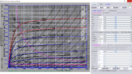
Here is revised12a6 RCA model as previous model draws too much grid1 current, hence VGOFF is adjusted to 0V from -1.8V and grid current scale readjusted. Attached shown is grid current drawn just slightly over driven, that is normal behaviors I believe.
Please try again:
Please try again:
Code:
**** 12A6 ******************************************
* Created on 08/05/2022 01:37 using paint_kip.jar
* www.dmitrynizh.com/tubeparams_image.htm
* Plate Curves image file: 12a6.png
* Data source link: <plate curves URL>
*----------------------------------------------------------------------------------
.SUBCKT 12A6 P G2 G K ; LTSpice tetrode.asy pinout
* .SUBCKT 12A6 P G K G2 ; Koren Pentode Pspice pinout
+ PARAMS: MU=9.4 KG1=6979.25 KP=110.52 KVB=339.16 VCT=2.657 EX=1.541 KG2=28485.35 KNEE=17.92 KVC=1.801
+ KLAM=2E-6 KLAMG=6.204E-8 KNEE2=0.201 KNEX=0.05115  KNK=-0.04158 KNG=0.008585 KNPL=0.625 KNSL=22.22 KNPR=164.07 KNSR=73.58
+ CCG=9P CGP=0.3P CCP=9P VGOFF=0 IGA=2.072 IGB=8.55 IGC=1.375 IGEX=0.1992
* Vp_MAX=500 Ip_MAX=160 Vg_step=5 Vg_start=10 Vg_count=13
* X_MIN=82 Y_MIN=28 X_SIZE=760 Y_SIZE=608 FSZ_X=1296 FSZ_Y=736 XYGrid=true
* Rp=1400 Vg_ac=20 P_max=7.5 Vg_qui=-20 Vp_qui=300
* showLoadLine=n showIp=y isDHP=n isPP=n isAsymPP=n isUL=n showDissipLimit=y
* showIg1=y isInputSnapped=y addLocalNFB=n
* XYProjections=n harmonicPlot=y dissipPlot=n
* UL=0.43 EG2=250 gridLevel2=y addKink=y isTanhKnee=y advSigmoid=n
*----------------------------------------------------------------------------------
RE1  7 0  1G    ; DUMMY SO NODE 7 HAS 2 CONNECTIONS
E1   7 0  VALUE=  ; E1 BREAKS UP LONG EQUATION FOR G1.
+{V(G2,K)/KP*LOG(1+EXP((1/MU+(VCT+V(G,K))/SQRT(KVB+V(G2,K)*V(G2,K)))*KP))}
RE2  6 0  1G    ; DUMMY SO NODE 6 HAS 2 CONNECTIONS
E2  6 0  VALUE={(PWR(V(7),EX)+PWRS(V(7),EX))} ; Kg1 times KIT current
RE21 21 0 1
E21  21 0 VALUE={V(6)/KG1*ATAN((V(P,K)+KNEX)/KNEE)*TANH(V(P,K)/KNEE2)} ; Ip with knee but no slope and no kink
RE22 22 0 1 ; E22: kink curr deviation for plate
E22  22 0 VALUE={V(21)*LIMIT(KNK-V(G,K)*KNG,0,0.3)*(-ATAN((V(P,K)-KNPL)/KNSL)+ATAN((V(P,K)-KNPR)/KNSR))}
G1   P  K  VALUE={V(21)*(1+KLAMG*V(P,K))+KLAM*V(P,K) + V(22)}
* Alexander Gurskii screen current, see audioXpress 2/2011, with slope and kink added
RE43 43 K 1G ; Dummy
E43  43 G2 VALUE={0} ; Dummy
G2   43 K  VALUE={V(6)/KG2*(KVC-ATAN((V(P,K)+KNEX)/KNEE)*TANH(V(P,K)/KNEE2))/(1+KLAMG*V(P,K))-V(22)}
RCP  P K  1G     ; FOR CONVERGENCE
C1   K G  {CCG}  ; CATHODE-GRID 1
C2   G P  {CGP}  ; GRID 1-PLATE
C3   K P  {CCP}  ; CATHODE-PLATE
RE23 G 0 1G
GG G K VALUE={(IGA+IGB/(IGC+V(P,K)))*(MU/KG1)*
+(PWR(V(G,K)-VGOFF,IGEX)+PWRS(V(G,K)-VGOFF,IGEX))}
.ENDS
*$
Attachments
Last edited:

Thanks again!Here is revised12a6 RCA model as previous model draws too much grid1 current, hence VGOFF is adjusted to 0V from -1.8V and grid current scale readjusted. Attached shown is grid current drawn just slightly over driven, that is normal behaviors I believe.
Please try again:
Code:**** 12A6 ****************************************** * Created on 08/05/2022 01:37 using paint_kip.jar * www.dmitrynizh.com/tubeparams_image.htm * Plate Curves image file: 12a6.png * Data source link: <plate curves URL> *---------------------------------------------------------------------------------- .SUBCKT 12A6 P G2 G K ; LTSpice tetrode.asy pinout * .SUBCKT 12A6 P G K G2 ; Koren Pentode Pspice pinout + PARAMS: MU=9.4 KG1=6979.25 KP=110.52 KVB=339.16 VCT=2.657 EX=1.541 KG2=28485.35 KNEE=17.92 KVC=1.801 + KLAM=2E-6 KLAMG=6.204E-8 KNEE2=0.201 KNEX=0.05115 KNK=-0.04158 KNG=0.008585 KNPL=0.625 KNSL=22.22 KNPR=164.07 KNSR=73.58 + CCG=9P CGP=0.3P CCP=9P VGOFF=0 IGA=2.072 IGB=8.55 IGC=1.375 IGEX=0.1992 * Vp_MAX=500 Ip_MAX=160 Vg_step=5 Vg_start=10 Vg_count=13 * X_MIN=82 Y_MIN=28 X_SIZE=760 Y_SIZE=608 FSZ_X=1296 FSZ_Y=736 XYGrid=true * Rp=1400 Vg_ac=20 P_max=7.5 Vg_qui=-20 Vp_qui=300 * showLoadLine=n showIp=y isDHP=n isPP=n isAsymPP=n isUL=n showDissipLimit=y * showIg1=y isInputSnapped=y addLocalNFB=n * XYProjections=n harmonicPlot=y dissipPlot=n * UL=0.43 EG2=250 gridLevel2=y addKink=y isTanhKnee=y advSigmoid=n *---------------------------------------------------------------------------------- RE1 7 0 1G ; DUMMY SO NODE 7 HAS 2 CONNECTIONS E1 7 0 VALUE= ; E1 BREAKS UP LONG EQUATION FOR G1. +{V(G2,K)/KP*LOG(1+EXP((1/MU+(VCT+V(G,K))/SQRT(KVB+V(G2,K)*V(G2,K)))*KP))} RE2 6 0 1G ; DUMMY SO NODE 6 HAS 2 CONNECTIONS E2 6 0 VALUE={(PWR(V(7),EX)+PWRS(V(7),EX))} ; Kg1 times KIT current RE21 21 0 1 E21 21 0 VALUE={V(6)/KG1*ATAN((V(P,K)+KNEX)/KNEE)*TANH(V(P,K)/KNEE2)} ; Ip with knee but no slope and no kink RE22 22 0 1 ; E22: kink curr deviation for plate E22 22 0 VALUE={V(21)*LIMIT(KNK-V(G,K)*KNG,0,0.3)*(-ATAN((V(P,K)-KNPL)/KNSL)+ATAN((V(P,K)-KNPR)/KNSR))} G1 P K VALUE={V(21)*(1+KLAMG*V(P,K))+KLAM*V(P,K) + V(22)} * Alexander Gurskii screen current, see audioXpress 2/2011, with slope and kink added RE43 43 K 1G ; Dummy E43 43 G2 VALUE={0} ; Dummy G2 43 K VALUE={V(6)/KG2*(KVC-ATAN((V(P,K)+KNEX)/KNEE)*TANH(V(P,K)/KNEE2))/(1+KLAMG*V(P,K))-V(22)} RCP P K 1G ; FOR CONVERGENCE C1 K G {CCG} ; CATHODE-GRID 1 C2 G P {CGP} ; GRID 1-PLATE C3 K P {CCP} ; CATHODE-PLATE RE23 G 0 1G GG G K VALUE={(IGA+IGB/(IGC+V(P,K)))*(MU/KG1)* +(PWR(V(G,K)-VGOFF,IGEX)+PWRS(V(G,K)-VGOFF,IGEX))} .ENDS *$
I don't see a lot of difference, and that weird clipping behavior is also still there.
It seems to be a quirk in LTSpice with certain models (not only tube related).
With some parts you just have to clip ever so slightly and it won't work it seems?
That grid current fix maynot address your issue. But I don't understand exactly what is the problem so as to give you a fix. To help us, can you post some snapshots of simulation or files?
I have seen this particular behaviour, where the slightest hint of clipping makes the simulation unstable. It's unpredictable, at least in my experience.Thanks again!
I don't see a lot of difference, and that weird clipping behavior is also still there.
It seems to be a quirk in LTSpice with certain models (not only tube related).
With some parts you just have to clip ever so slightly and it won't work it seems?
During clipping grid 1 went into oscillation esp with cap coupled input. If in A2 (direct coupled) mode rather than A1(cap coupled), it's fine. So I want to post here a less complex grid current model (RGI), but less accurate where everything else is not affected.
12a6 RGI grid current model:
12a6 RGI grid current model:
Code:
**** 12A6 ******************************************
* Created on 08/05/2022 21:08 using paint_kip.jar
* www.dmitrynizh.com/tubeparams_image.htm
* Plate Curves image file: 12a6.png
* Data source link: <plate curves URL>
*----------------------------------------------------------------------------------
.SUBCKT 12A6 P G2 G K ; LTSpice tetrode.asy pinout
* .SUBCKT 12A6 P G K G2 ; Koren Pentode Pspice pinout
+ PARAMS: MU=9.4 KG1=6979.25 KP=110.52 KVB=339.16 VCT=2.657 EX=1.541 KG2=23357.99 KNEE=17.92 KVC=1.873
+ KLAM=2E-6 KLAMG=6.204E-8 KNEE2=0.201 KNEX=0.05115  KNK=-0.04158 KNG=0.008585 KNPL=0.625 KNSL=22.22 KNPR=164.07 KNSR=73.58
+ CCG=9P CGP=0.3P CCP=9P RGI=960.0
* Vp_MAX=500 Ip_MAX=160 Vg_step=5 Vg_start=10 Vg_count=13
* X_MIN=82 Y_MIN=28 X_SIZE=760 Y_SIZE=608 FSZ_X=1296 FSZ_Y=736 XYGrid=true
* Rp=1400 Vg_ac=20 P_max=7.5 Vg_qui=-20 Vp_qui=300
* showLoadLine=n showIp=y isDHP=n isPP=n isAsymPP=n isUL=n showDissipLimit=y
* showIg1=y isInputSnapped=y addLocalNFB=n
* XYProjections=n harmonicPlot=y dissipPlot=n
* UL=0.43 EG2=250 gridLevel2=n addKink=y isTanhKnee=y advSigmoid=n
*----------------------------------------------------------------------------------
RE1  7 0  1G    ; DUMMY SO NODE 7 HAS 2 CONNECTIONS
E1   7 0  VALUE=  ; E1 BREAKS UP LONG EQUATION FOR G1.
+{V(G2,K)/KP*LOG(1+EXP((1/MU+(VCT+V(G,K))/SQRT(KVB+V(G2,K)*V(G2,K)))*KP))}
RE2  6 0  1G    ; DUMMY SO NODE 6 HAS 2 CONNECTIONS
E2  6 0  VALUE={(PWR(V(7),EX)+PWRS(V(7),EX))} ; Kg1 times KIT current
RE21 21 0 1
E21  21 0 VALUE={V(6)/KG1*ATAN((V(P,K)+KNEX)/KNEE)*TANH(V(P,K)/KNEE2)} ; Ip with knee but no slope and no kink
RE22 22 0 1 ; E22: kink curr deviation for plate
E22  22 0 VALUE={V(21)*LIMIT(KNK-V(G,K)*KNG,0,0.3)*(-ATAN((V(P,K)-KNPL)/KNSL)+ATAN((V(P,K)-KNPR)/KNSR))}
G1   P  K  VALUE={V(21)*(1+KLAMG*V(P,K))+KLAM*V(P,K) + V(22)}
* Alexander Gurskii screen current, see audioXpress 2/2011, with slope and kink added
RE43 43 K 1G ; Dummy
E43  43 G2 VALUE={0} ; Dummy
G2   43 K  VALUE={V(6)/KG2*(KVC-ATAN((V(P,K)+KNEX)/KNEE)*TANH(V(P,K)/KNEE2))/(1+KLAMG*V(P,K))-V(22)}
RCP  P K  1G     ; FOR CONVERGENCE
C1   K G  {CCG}  ; CATHODE-GRID 1
C2   G P  {CGP}  ; GRID 1-PLATE
C3   K P  {CCP}  ; CATHODE-PLATE
R1   G 5  {RGI}  ; FOR GRID CURRENT
D3   5 K  DX     ; FOR GRID CURRENT }
.MODEL DX D(IS=1N RS=1 CJO=10PF TT=1N)
.ENDS
*$
Last edited:
Thank you so much again for all the effort!!During clipping grid 1 went into oscillation esp with cap coupled input. If in A2 (direct coupled) mode rather than A1(cap coupled), it's fine. So I want to post here a less complex grid current model (RGI), but less accurate where everything else is not affected.
12a6 RGI grid current model:
Code:**** 12A6 ****************************************** * Created on 08/05/2022 21:08 using paint_kip.jar * www.dmitrynizh.com/tubeparams_image.htm * Plate Curves image file: 12a6.png * Data source link: <plate curves URL> *---------------------------------------------------------------------------------- .SUBCKT 12A6 P G2 G K ; LTSpice tetrode.asy pinout * .SUBCKT 12A6 P G K G2 ; Koren Pentode Pspice pinout + PARAMS: MU=9.4 KG1=6979.25 KP=110.52 KVB=339.16 VCT=2.657 EX=1.541 KG2=23357.99 KNEE=17.92 KVC=1.873 + KLAM=2E-6 KLAMG=6.204E-8 KNEE2=0.201 KNEX=0.05115 KNK=-0.04158 KNG=0.008585 KNPL=0.625 KNSL=22.22 KNPR=164.07 KNSR=73.58 + CCG=9P CGP=0.3P CCP=9P RGI=960.0 * Vp_MAX=500 Ip_MAX=160 Vg_step=5 Vg_start=10 Vg_count=13 * X_MIN=82 Y_MIN=28 X_SIZE=760 Y_SIZE=608 FSZ_X=1296 FSZ_Y=736 XYGrid=true * Rp=1400 Vg_ac=20 P_max=7.5 Vg_qui=-20 Vp_qui=300 * showLoadLine=n showIp=y isDHP=n isPP=n isAsymPP=n isUL=n showDissipLimit=y * showIg1=y isInputSnapped=y addLocalNFB=n * XYProjections=n harmonicPlot=y dissipPlot=n * UL=0.43 EG2=250 gridLevel2=n addKink=y isTanhKnee=y advSigmoid=n *---------------------------------------------------------------------------------- RE1 7 0 1G ; DUMMY SO NODE 7 HAS 2 CONNECTIONS E1 7 0 VALUE= ; E1 BREAKS UP LONG EQUATION FOR G1. +{V(G2,K)/KP*LOG(1+EXP((1/MU+(VCT+V(G,K))/SQRT(KVB+V(G2,K)*V(G2,K)))*KP))} RE2 6 0 1G ; DUMMY SO NODE 6 HAS 2 CONNECTIONS E2 6 0 VALUE={(PWR(V(7),EX)+PWRS(V(7),EX))} ; Kg1 times KIT current RE21 21 0 1 E21 21 0 VALUE={V(6)/KG1*ATAN((V(P,K)+KNEX)/KNEE)*TANH(V(P,K)/KNEE2)} ; Ip with knee but no slope and no kink RE22 22 0 1 ; E22: kink curr deviation for plate E22 22 0 VALUE={V(21)*LIMIT(KNK-V(G,K)*KNG,0,0.3)*(-ATAN((V(P,K)-KNPL)/KNSL)+ATAN((V(P,K)-KNPR)/KNSR))} G1 P K VALUE={V(21)*(1+KLAMG*V(P,K))+KLAM*V(P,K) + V(22)} * Alexander Gurskii screen current, see audioXpress 2/2011, with slope and kink added RE43 43 K 1G ; Dummy E43 43 G2 VALUE={0} ; Dummy G2 43 K VALUE={V(6)/KG2*(KVC-ATAN((V(P,K)+KNEX)/KNEE)*TANH(V(P,K)/KNEE2))/(1+KLAMG*V(P,K))-V(22)} RCP P K 1G ; FOR CONVERGENCE C1 K G {CCG} ; CATHODE-GRID 1 C2 G P {CGP} ; GRID 1-PLATE C3 K P {CCP} ; CATHODE-PLATE R1 G 5 {RGI} ; FOR GRID CURRENT D3 5 K DX ; FOR GRID CURRENT } .MODEL DX D(IS=1N RS=1 CJO=10PF TT=1N) .ENDS *$
Will check later, currently on holiday 🙂
I know this thread is really for LTspice tube models, but I was wondering if someone has an LTspice simulation file with models for a push-pull tube power amp? Doesn't matter which tubes, I just want to check something out.
Would save me a lot of time, appreciated!
Jan
Would save me a lot of time, appreciated!
Jan
Here is one, based on EICO HF-89, built first, then simulated.I know this thread is really for LTspice tube models, but I was wondering if someone has an LTspice simulation file with models for a push-pull tube power amp? Doesn't matter which tubes, I just want to check something out.
Would save me a lot of time, appreciated!
Jan
Attachments
I will send a PM with a zip fileThanks, that's a nice circuit for me to play with. Could you also post the .asc?
Jan
Edit: my post shows the asc attached, can you see it?
Missing stuff in the archive.Yes I do, sorry I missed it.
Missing triode-w1-ddtransppul , probably a .inc file?
Jan
Jan
Attachments
Almost! I think I also need .inc c:\Users\jcalv\Google Drive\Electronics\LTSpice\6L6.inc or at least the 6L6.inc .
There are 3 other .inc files which I believe I do not need.
Jan
There are 3 other .inc files which I believe I do not need.
Jan
Attached, just rename it to 6L6.incAlmost! I think I also need .inc c:\Users\jcalv\Google Drive\Electronics\LTSpice\6L6.inc or at least the 6L6.inc .
There are 3 other .inc files which I believe I do not need.
Jan
Attachments
- Home
- Amplifiers
- Tubes / Valves
- Vacuum Tube SPICE Models