Is there a model for the 845 and the 805 in this thread? I couldn't seem to find it. Thanks v much
https://www.diyaudio.com/community/attachments/ayumi_ltspice-zip.689353/
Download the above zip file it contains 845.inc.
Download the above zip file it contains 845.inc.
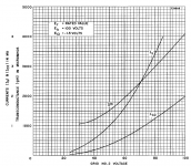
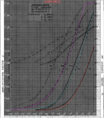
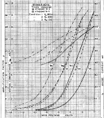
Thanks Koonw, somehow I missed that. Any idea how accurately does the I-V characteristics follow the RCA or Amperex datasheet on https://frank.pocnet.net/sheets/111/8/845.pdfhttps://www.diyaudio.com/community/attachments/ayumi_ltspice-zip.689353/
Download the above zip file it contains 845.inc.
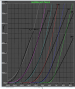
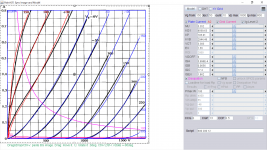
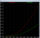
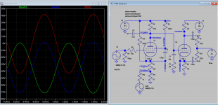
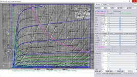
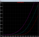
Hi, welcome, see attached transfer curve plot when compared to the curve you posted. Here is 845 model I painted:
Code:
**** 845 ** Advanced Grid Current **********************************
* Created on 09/02/2022 12:14 using paint_kit.jar 3.1
* www.dmitrynizh.com/tubeparams_image.htm
* Plate Curves image file: 845.png
* Data source link:
*----------------------------------------------------------------------------------
.SUBCKT 845 1 2 3 ; Plate Grid Cathode
+ PARAMS: CCG=6P  CGP=13P CCP=6.5P
+ MU=5.352 KG1=8229.88 KP=105.01 KVB=2738.35 VCT=1.928 EX=1.519
+ VGOFF=0 IGA=5.996E-4 IGB=0.0656 IGC=17.4 IGEX=1.862
* Vp_MAX=1800 Ip_MAX=800 Vg_step=50 Vg_start=150 Vg_count=10
* Rp=4000 Vg_ac=55 P_max=100 Vg_qui=-48 Vp_qui=300
* X_MIN=36 Y_MIN=26 X_SIZE=661 Y_SIZE=616 FSZ_X=1296 FSZ_Y=736 XYGrid=false
* showLoadLine=n showIp=y isDHT=n isPP=n isAsymPP=n showDissipLimit=y
* showIg1=y gridLevel2=y isInputSnapped=n
* XYProjections=n harmonicPlot=n dissipPlot=n
*----------------------------------------------------------------------------------
E1 7 0 VALUE={V(1,3)/KP*LOG(1+EXP(KP*(1/MU+(VCT+V(2,3))/SQRT(KVB+V(1,3)*V(1,3)))))}
RE1 7 0 1G  ; TO AVOID FLOATING NODES
G1 1 3 VALUE={(PWR(V(7),EX)+PWRS(V(7),EX))/KG1}
RCP 1 3 1G   ; TO AVOID FLOATING NODES
C1 2 3 {CCG} ; CATHODE-GRID
C2 2 1 {CGP} ; GRID=PLATE
C3 1 3 {CCP} ; CATHODE-PLATE
RE2 2 0 1G
EGC 8 0 VALUE={V(2,3)-VGOFF} ; POSITIVE GRID THRESHOLD
GG 2 3 VALUE={(IGA+IGB/(IGC+V(1,3)))*(MU/KG1)*(PWR(V(8),IGEX)+PWRS(V(8),IGEX))}
.ENDS
*$
Attachments
This is 845 Amprex model, which is close to previous model T110-1:
Code:
**** 845 Amprex** Advanced Grid Current *************************posted*********
* Created on 09/02/2022 16:43 using paint_kit.jar 3.1
* www.dmitrynizh.com/tubeparams_image.htm
* Plate Curves image file: 845-amp.png
* Data source link:
*----------------------------------------------------------------------------------
.SUBCKT 845-AMP 1 2 3 ; Plate Grid Cathode
+ PARAMS: CCG=5P  CGP=11.5P CCP=3.5P
+ MU=5.727 KG1=795.94 KP=65.55 KVB=42766.21 VCT=-12.68 EX=1.13
+ VGOFF=0 IGA=4.947E-5 IGB=0.0656 IGC=17.4 IGEX=1.862
* Vp_MAX=2500 Ip_MAX=190 Vg_step=50 Vg_start=0 Vg_count=15
* Rp=4000 Vg_ac=55 P_max=60 Vg_qui=-48 Vp_qui=300
* X_MIN=49 Y_MIN=6 X_SIZE=763 Y_SIZE=585 FSZ_X=1296 FSZ_Y=736 XYGrid=false
* showLoadLine=n showIp=y isDHT=n isPP=n isAsymPP=n showDissipLimit=y
* showIg1=y gridLevel2=y isInputSnapped=n
* XYProjections=n harmonicPlot=n dissipPlot=n
*----------------------------------------------------------------------------------
E1 7 0 VALUE={V(1,3)/KP*LOG(1+EXP(KP*(1/MU+(VCT+V(2,3))/SQRT(KVB+V(1,3)*V(1,3)))))}
RE1 7 0 1G  ; TO AVOID FLOATING NODES
G1 1 3 VALUE={(PWR(V(7),EX)+PWRS(V(7),EX))/KG1}
RCP 1 3 1G   ; TO AVOID FLOATING NODES
C1 2 3 {CCG} ; CATHODE-GRID
C2 2 1 {CGP} ; GRID=PLATE
C3 1 3 {CCP} ; CATHODE-PLATE
RE2 2 0 1G
EGC 8 0 VALUE={V(2,3)-VGOFF} ; POSITIVE GRID THRESHOLD
GG 2 3 VALUE={(IGA+IGB/(IGC+V(1,3)))*(MU/KG1)*(PWR(V(8),IGEX)+PWRS(V(8),IGEX))}
.ENDS
*$
Attachments
I have to dive deep where I got it from, but I have been using some tube models were the tube type can be selected inside LTSpice itself. That saves a lot of those issues.Almost! I think I also need .inc c:\Users\jcalv\Google Drive\Electronics\LTSpice\6L6.inc or at least the 6L6.inc .
There are 3 other .inc files which I believe I do not need.
Jan
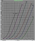
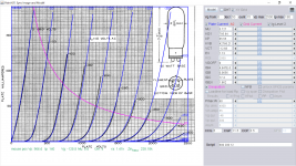
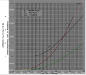
Thanks very much, this new data set gives much better fit to the Amperex 845 data.This is 845 Amprex model, which is close to previous model T110-1:
Code:**** 845 Amprex** Advanced Grid Current *************************posted********* * Created on 09/02/2022 16:43 using paint_kit.jar 3.1 * www.dmitrynizh.com/tubeparams_image.htm * Plate Curves image file: 845-amp.png * Data source link: *---------------------------------------------------------------------------------- .SUBCKT 845-AMP 1 2 3 ; Plate Grid Cathode + PARAMS: CCG=5P CGP=11.5P CCP=3.5P + MU=5.727 KG1=795.94 KP=65.55 KVB=42766.21 VCT=-12.68 EX=1.13 + VGOFF=0 IGA=4.947E-5 IGB=0.0656 IGC=17.4 IGEX=1.862 * Vp_MAX=2500 Ip_MAX=190 Vg_step=50 Vg_start=0 Vg_count=15 * Rp=4000 Vg_ac=55 P_max=60 Vg_qui=-48 Vp_qui=300 * X_MIN=49 Y_MIN=6 X_SIZE=763 Y_SIZE=585 FSZ_X=1296 FSZ_Y=736 XYGrid=false * showLoadLine=n showIp=y isDHT=n isPP=n isAsymPP=n showDissipLimit=y * showIg1=y gridLevel2=y isInputSnapped=n * XYProjections=n harmonicPlot=n dissipPlot=n *---------------------------------------------------------------------------------- E1 7 0 VALUE={V(1,3)/KP*LOG(1+EXP(KP*(1/MU+(VCT+V(2,3))/SQRT(KVB+V(1,3)*V(1,3)))))} RE1 7 0 1G ; TO AVOID FLOATING NODES G1 1 3 VALUE={(PWR(V(7),EX)+PWRS(V(7),EX))/KG1} RCP 1 3 1G ; TO AVOID FLOATING NODES C1 2 3 {CCG} ; CATHODE-GRID C2 2 1 {CGP} ; GRID=PLATE C3 1 3 {CCP} ; CATHODE-PLATE RE2 2 0 1G EGC 8 0 VALUE={V(2,3)-VGOFF} ; POSITIVE GRID THRESHOLD GG 2 3 VALUE={(IGA+IGB/(IGC+V(1,3)))*(MU/KG1)*(PWR(V(8),IGEX)+PWRS(V(8),IGEX))} .ENDS *$
7199
Here are the model for 7199 pentode and triode section:
Pentode
Code:* [URL="http://www.dmitrynizh.com/tubeparams_image.htm"]www.dmitrynizh.com/tubeparams_image.htm[/URL] * Plate Curves image file: 7199-p.png * Data source link: <plate curves URL> *---------------------------------------------------------------------------------- .SUBCKT 7199_P P G2 G K ; LTSpice tetrode.asy pinout * .SUBCKT 7199_P P G K G2 ; Koren Pentode Pspice pinout + PARAMS: MU=44.4 KG1=544.52 KP=108.69 KVB=1078.62 VCT=-0.4676 EX=1.284 KG2=741.65 KNEE=327.17 KVC=2.32 + KLAM=9.971E-8 KLAMG=1.551E-4 KD=4.862 KC=1.105E-9 KR1=0.3576 KR2=0.02688 KVBG=0.01121 KB1=0.544 KB2=6.42 KB3=2.46 KB4=0.1404 KVBGI=0.01115 KNK=0.1675 KNG=0.05509 KNPL=0.02375 KNSL=0.0739 KNPR=0.2612 KNSR=14.72 + CCG=3P CGP=1.4P CCP=1.9P VGOFF=-1.5 IGA=0.002687 IGB=0.05343 IGC=13.36 IGEX=1.764 * Vp_MAX=300 Ip_MAX=25 Vg_step=1 Vg_start=0 Vg_count=11 * X_MIN=49 Y_MIN=10 X_SIZE=780 Y_SIZE=657 FSZ_X=1287 FSZ_Y=723 XYGrid=false * Rp=1400 Vg_ac=20 P_max=3 Vg_qui=-5 Vp_qui=300 * showLoadLine=n showIp=y isDHP=n isPP=n isAsymPP=n isUL=n showDissipLimit=y * showIg1=y isInputSnapped=y addLocalNFB=n * XYProjections=n harmonicPlot=y dissipPlot=n * UL=0.43 EG2=130 gridLevel2=y addKink=y isTanhKnee=n advSigmoid=y *---------------------------------------------------------------------------------- RE1 7 0 1G ; DUMMY SO NODE 7 HAS 2 CONNECTIONS E1 7 0 VALUE= ; E1 BREAKS UP LONG EQUATION FOR G1. +{V(G2,K)/KP*LOG(1+EXP((1/MU+(VCT+V(G,K))/SQRT(KVB+V(G2,K)*V(G2,K)))*KP))} RE2 6 0 1G ; DUMMY SO NODE 6 HAS 2 CONNECTIONS E2 6 0 VALUE={(PWR(V(7),EX)+PWRS(V(7),EX))} ; Kg1 times KIT current E4 8 0 VALUE={V(P,K)/KNEE/(KVBGI+V(6)*KVBG)} E5 81 0 VALUE={PWR(V(8),KB1)} E6 82 0 VALUE={PWR(V(8),KB2)} E7 83 0 VALUE={PWR(V(8),KB3)} E8 9 0 VALUE={PWR(1-EXP(-V(81)*(KC+KR1*V(82))/(KD+KR2*V(83))),KB4)*1.5708} RE4 8 0 1 RE5 81 0 1 RE6 82 0 1 RE7 83 0 1 RE8 9 0 1 RE21 21 0 1 E21 21 0 VALUE={V(6)/KG1*V(9)} ; Ip with knee but no slope and no kink RE22 22 0 1 ; E22: kink curr deviation for plate E22 22 0 VALUE={V(21)*LIMIT(KNK-V(G,K)*KNG,0,0.3)*(-ATAN((V(P,K)-KNPL)/KNSL)+ATAN((V(P,K)-KNPR)/KNSR))} G1 P K VALUE={V(21)*(1+KLAMG*V(P,K))+KLAM*V(P,K) + V(22)} G2 G2 K VALUE={V(6)/KG2*(KVC-V(9))/(1+KLAMG*V(P,K)) - V(22)} RCP P K 1G ; FOR CONVERGENCE C1 K G {CCG} ; CATHODE-GRID 1 C2 G P {CGP} ; GRID 1-PLATE C3 K P {CCP} ; CATHODE-PLATE RE23 G 0 1G GG G K VALUE={(IGA+IGB/(IGC+V(P,K)))*(MU/KG1)* +(PWR(V(G,K)-VGOFF,IGEX)+PWRS(V(G,K)-VGOFF,IGEX))} .ENDS *$
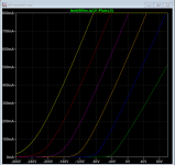
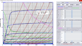
I have used this 7199 pentode model for simulating the Dynaco St-70. I have compared the model with published plots in the attached 7199.pdf datasheet. I can accurately duplicate the Plate Characteristics curve on pg. 5, in which the screen grid is 130 V. The same model performs poorly modeling the Transfer Characteristics curve on pg. 6. Here, the screen is 50 V. LTSpice is producing both plate and screen currents that are roughly half of the published values, over a range of grid 1 voltages. This is as if the model was generated using a screen grid voltage of 130, and it falls apart with smaller screen voltages.
Back to the Dynaco simulation, the screen runs at a lower voltage, and the pentode is not conducting nearly enough for the phase splitter stage to work (pentode plate voltage way too high). Does anyone have experience or insight into this pentode model? Or how to adjust the model to handle a range of screen potentials?
Thanks in advance,
Bill S.
Attachments
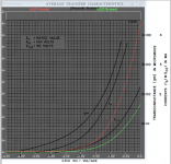
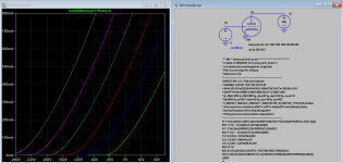
As no triode connected curve is available, param VCT can not be precisely specified. So by trial and error, the transfer curve has finally matched the original by adjusting VCT (that shift the curve left or right) Give it another try:
Code:
**** 7199_P ******************************************
* Created on 09/08/2022 01:37 using paint_kip.jar
* www.dmitrynizh.com/tubeparams_image.htm
* Plate Curves image file: 7199-p.png
* Data source link: <plate curves URL>
*----------------------------------------------------------------------------------
.SUBCKT 7199_P P G2 G K ; LTSpice tetrode.asy pinout
* .SUBCKT 7199_P P G K G2 ; Koren Pentode Pspice pinout
+ PARAMS: MU=55.34 KG1=769.79 KP=104.27 KVB=1078.62 VCT=0.55 EX=1.427 KG2=1174.09 KNEE=1014.48 KVC=2.388
+ KLAM=9.971E-8 KLAMG=1.971E-4  KD=4.272E-6 KC=1.188E-10 KR1=1.624 KR2=0.02688 KVBG=0.00734 KB1=1.95 KB2=8.603 KB3=2.46 KB4=0.1404 KVBGI=1.589E-4 KNK=0.1675 KNG=0.05509 KNPL=0.02375 KNSL=0.0739 KNPR=0.2612 KNSR=14.72
+ CCG=3P CGP=1.4P CCP=1.9P VGOFF=-1.5 IGA=0.002687 IGB=0.05343 IGC=13.36 IGEX=1.764
* Vp_MAX=300 Ip_MAX=25 Vg_step=1 Vg_start=0 Vg_count=11
* X_MIN=49 Y_MIN=10 X_SIZE=777 Y_SIZE=657 FSZ_X=1296 FSZ_Y=736 XYGrid=false
* Rp=1400 Vg_ac=20 P_max=3 Vg_qui=-5 Vp_qui=300
* showLoadLine=n showIp=y isDHP=n isPP=n isAsymPP=n isUL=n showDissipLimit=y
* showIg1=y isInputSnapped=y addLocalNFB=n
* XYProjections=n harmonicPlot=y dissipPlot=n
* UL=0.43 EG2=130 gridLevel2=y addKink=y isTanhKnee=n advSigmoid=y
*----------------------------------------------------------------------------------
RE1  7 0  1G    ; DUMMY SO NODE 7 HAS 2 CONNECTIONS
E1   7 0  VALUE=  ; E1 BREAKS UP LONG EQUATION FOR G1.
+{V(G2,K)/KP*LOG(1+EXP((1/MU+(VCT+V(G,K))/SQRT(KVB+V(G2,K)*V(G2,K)))*KP))}
RE2  6 0  1G    ; DUMMY SO NODE 6 HAS 2 CONNECTIONS
E2  6 0  VALUE={(PWR(V(7),EX)+PWRS(V(7),EX))} ; Kg1 times KIT current
E4   8 0  VALUE={V(P,K)/KNEE/(KVBGI+V(6)*KVBG)}
E5  81 0  VALUE={PWR(V(8),KB1)}
E6  82 0  VALUE={PWR(V(8),KB2)}
E7  83 0  VALUE={PWR(V(8),KB3)}
E8   9 0  VALUE={PWR(1-EXP(-V(81)*(KC+KR1*V(82))/(KD+KR2*V(83))),KB4)*1.5708}
RE4  8 0  1
RE5 81 0  1
RE6 82 0  1
RE7 83 0  1
RE8  9 0  1
RE21 21 0 1
E21  21 0 VALUE={V(6)/KG1*V(9)} ; Ip with knee but no slope and no kink
RE22 22 0 1 ; E22: kink curr deviation for plate
E22  22 0 VALUE={V(21)*LIMIT(KNK-V(G,K)*KNG,0,0.3)*(-ATAN((V(P,K)-KNPL)/KNSL)+ATAN((V(P,K)-KNPR)/KNSR))}
G1   P K  VALUE={V(21)*(1+KLAMG*V(P,K))+KLAM*V(P,K) + V(22)}
G2   G2 K  VALUE={V(6)/KG2*(KVC-V(9))/(1+KLAMG*V(P,K)) - V(22)}
RCP  P K  1G     ; FOR CONVERGENCE
C1   K G  {CCG}  ; CATHODE-GRID 1
C2   G P  {CGP}  ; GRID 1-PLATE
C3   K P  {CCP}  ; CATHODE-PLATE
RE23 G 0 1G
GG G K VALUE={(IGA+IGB/(IGC+V(P,K)))*(MU/KG1)*
+(PWR(V(G,K)-VGOFF,IGEX)+PWRS(V(G,K)-VGOFF,IGEX))}
.ENDS
*$
Attachments

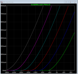
I further adjusted param VGOFF to 0, and verified with another schematic measurement:
https://www.diyaudio.com/community/threads/dynaco-st70-pentode-triode-voltages.333997/
https://www.diyaudio.com/community/threads/dynaco-st70-pentode-triode-voltages.333997/
Code:
**** 7199_P ******************************************
* Created on 09/11/2022 02:13 using paint_kip.jar
* www.dmitrynizh.com/tubeparams_image.htm
* Plate Curves image file: 7199-p.png
* Data source link: <plate curves URL>
*----------------------------------------------------------------------------------
.SUBCKT 7199_P P G2 G K ; LTSpice tetrode.asy pinout
* .SUBCKT 7199_P P G K G2 ; Koren Pentode Pspice pinout
+ PARAMS: MU=55.34 KG1=754.39 KP=103.23 KVB=97.08 VCT=0.55 EX=1.427 KG2=1174.09 KNEE=1014.48 KVC=2.388
+ KLAM=9.971E-8 KLAMG=1.597E-4  KD=4.272E-6 KC=1.188E-10 KR1=1.624 KR2=0.02688 KVBG=0.00734 KB1=1.95 KB2=8.603 KB3=2.46 KB4=0.1404 KVBGI=1.589E-4 KNK=0.1926 KNG=0.2468 KNPL=0.0266 KNSL=0.06947 KNPR=0.1724 KNSR=14.13
+ CCG=3P CGP=1.4P CCP=1.9P VGOFF=0 IGA=0.002687 IGB=0.05343 IGC=13.36 IGEX=1.764
* Vp_MAX=300 Ip_MAX=25 Vg_step=1 Vg_start=0 Vg_count=11
* X_MIN=49 Y_MIN=10 X_SIZE=777 Y_SIZE=657 FSZ_X=1296 FSZ_Y=736 XYGrid=false
* Rp=1400 Vg_ac=20 P_max=3 Vg_qui=-5 Vp_qui=300
* showLoadLine=n showIp=y isDHP=n isPP=n isAsymPP=n isUL=n showDissipLimit=y
* showIg1=y isInputSnapped=y addLocalNFB=n
* XYProjections=n harmonicPlot=y dissipPlot=n
* UL=0.43 EG2=130 gridLevel2=y addKink=y isTanhKnee=n advSigmoid=y
*----------------------------------------------------------------------------------
RE1  7 0  1G    ; DUMMY SO NODE 7 HAS 2 CONNECTIONS
E1   7 0  VALUE=  ; E1 BREAKS UP LONG EQUATION FOR G1.
+{V(G2,K)/KP*LOG(1+EXP((1/MU+(VCT+V(G,K))/SQRT(KVB+V(G2,K)*V(G2,K)))*KP))}
RE2  6 0  1G    ; DUMMY SO NODE 6 HAS 2 CONNECTIONS
E2  6 0  VALUE={(PWR(V(7),EX)+PWRS(V(7),EX))} ; Kg1 times KIT current
E4   8 0  VALUE={V(P,K)/KNEE/(KVBGI+V(6)*KVBG)}
E5  81 0  VALUE={PWR(V(8),KB1)}
E6  82 0  VALUE={PWR(V(8),KB2)}
E7  83 0  VALUE={PWR(V(8),KB3)}
E8   9 0  VALUE={PWR(1-EXP(-V(81)*(KC+KR1*V(82))/(KD+KR2*V(83))),KB4)*1.5708}
RE4  8 0  1
RE5 81 0  1
RE6 82 0  1
RE7 83 0  1
RE8  9 0  1
RE21 21 0 1
E21  21 0 VALUE={V(6)/KG1*V(9)} ; Ip with knee but no slope and no kink
RE22 22 0 1 ; E22: kink curr deviation for plate
E22  22 0 VALUE={V(21)*LIMIT(KNK-V(G,K)*KNG,0,0.3)*(-ATAN((V(P,K)-KNPL)/KNSL)+ATAN((V(P,K)-KNPR)/KNSR))}
G1   P K  VALUE={V(21)*(1+KLAMG*V(P,K))+KLAM*V(P,K) + V(22)}
G2   G2 K  VALUE={V(6)/KG2*(KVC-V(9))/(1+KLAMG*V(P,K)) - V(22)}
RCP  P K  1G     ; FOR CONVERGENCE
C1   K G  {CCG}  ; CATHODE-GRID 1
C2   G P  {CGP}  ; GRID 1-PLATE
C3   K P  {CCP}  ; CATHODE-PLATE
RE23 G 0 1G
GG G K VALUE={(IGA+IGB/(IGC+V(P,K)))*(MU/KG1)*
+(PWR(V(G,K)-VGOFF,IGEX)+PWRS(V(G,K)-VGOFF,IGEX))}
.ENDS
*$
Attachments
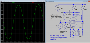
I also have done a gain test of 7199 pentode and verified and agreed with method found here:
https://www.one-electron.com/Archives/RCA/RCA-AppNotes/RCA 1959 AN-183 Applications of the 7199 in Hi-Fi Audio Equipment.pdf
https://www.one-electron.com/Archives/RCA/RCA-AppNotes/RCA 1959 AN-183 Applications of the 7199 in Hi-Fi Audio Equipment.pdf
Attachments
Last edited:
Hello!
Is there a model for the 6CH6/EL821 around? Tried googling around to no avail.
Thanks!
Is there a model for the 6CH6/EL821 around? Tried googling around to no avail.
Thanks!
Triode curve for 6CH6 to be found here, page 19: https://frank.pocnet.net/sheets/184/6/6CH6.pdfHello!
Is there a model for the 6CH6/EL821 around? Tried googling around to no avail.
Thanks!
Thanks! I had the datasheet with the curves, I was hoping there was a ready LTSpice model.Triode curve for 6CH6 to be found here, page 19: https://frank.pocnet.net/sheets/184/6/6CH6.pdf
Try this STC/Brimar 6ch6 pentode model:
Code:
*** 6CH6_P ******************************************
* Created on 09/16/2022 01:44 using paint_kip.jar
* www.dmitrynizh.com/tubeparams_image.htm
* Plate Curves image file: 6ch6-p.png
* Data source link: <plate curves URL>
*----------------------------------------------------------------------------------
.SUBCKT 6CH6_P P G2 G K ; LTSpice tetrode.asy pinout
* .SUBCKT 6CH6_P P G K G2 ; Koren Pentode Pspice pinout
+ PARAMS: MU=32.34 KG1=161.59 KP=141.61 KVB=7004.28 VCT=-2.48 EX=0.929 KG2=197.82 KNEE=22.39 KVC=1.839
+ KLAM=5E-9 KLAMG=4.757E-4  KD=78.41 KC=0.02893 KR1=8.15E-4 KR2=0.03169 KVBG=1.641E-7 KB1=0.5652 KB2=2.289 KB3=2.366 KB4=55.99 KVBGI=2.618E-5 KNK=0.03384 KNG=1.068E-4 KNPL=0.003524 KNSL=8.783E-4 KNPR=287.7 KNSR=37835.67
+ CCG=14P CGP=0.25P CCP=5P VGOFF=-0.6 IGA=0.001 IGB=0.3 IGC=8 IGEX=2
* Vp_MAX=500 Ip_MAX=100 Vg_step=2 Vg_start=0 Vg_count=13
* X_MIN=111 Y_MIN=19 X_SIZE=733 Y_SIZE=588 FSZ_X=1296 FSZ_Y=736 XYGrid=false
* Rp=1400 Vg_ac=20 P_max=12 Vg_qui=-12 Vp_qui=300
* showLoadLine=n showIp=y isDHP=n isPP=n isAsymPP=n isUL=n showDissipLimit=y
* showIg1=y isInputSnapped=y addLocalNFB=n
* XYProjections=n harmonicPlot=y dissipPlot=n
* UL=0.43 EG2=250 gridLevel2=y addKink=y isTanhKnee=n advSigmoid=y
*----------------------------------------------------------------------------------
RE1  7 0  1G    ; DUMMY SO NODE 7 HAS 2 CONNECTIONS
E1   7 0  VALUE=  ; E1 BREAKS UP LONG EQUATION FOR G1.
+{V(G2,K)/KP*LOG(1+EXP((1/MU+(VCT+V(G,K))/SQRT(KVB+V(G2,K)*V(G2,K)))*KP))}
RE2  6 0  1G    ; DUMMY SO NODE 6 HAS 2 CONNECTIONS
E2  6 0  VALUE={(PWR(V(7),EX)+PWRS(V(7),EX))} ; Kg1 times KIT current
E4   8 0  VALUE={V(P,K)/KNEE/(KVBGI+V(6)*KVBG)}
E5  81 0  VALUE={PWR(V(8),KB1)}
E6  82 0  VALUE={PWR(V(8),KB2)}
E7  83 0  VALUE={PWR(V(8),KB3)}
E8   9 0  VALUE={PWR(1-EXP(-V(81)*(KC+KR1*V(82))/(KD+KR2*V(83))),KB4)*1.5708}
RE4  8 0  1
RE5 81 0  1
RE6 82 0  1
RE7 83 0  1
RE8  9 0  1
RE21 21 0 1
E21  21 0 VALUE={V(6)/KG1*V(9)} ; Ip with knee but no slope and no kink
RE22 22 0 1 ; E22: kink curr deviation for plate
E22  22 0 VALUE={V(21)*LIMIT(KNK-V(G,K)*KNG,0,0.3)*(-ATAN((V(P,K)-KNPL)/KNSL)+ATAN((V(P,K)-KNPR)/KNSR))}
G1   P K  VALUE={V(21)*(1+KLAMG*V(P,K))+KLAM*V(P,K) + V(22)}
G2   G2 K  VALUE={V(6)/KG2*(KVC-V(9))/(1+KLAMG*V(P,K)) - V(22)}
RCP  P K  1G     ; FOR CONVERGENCE
C1   K G  {CCG}  ; CATHODE-GRID 1
C2   G P  {CGP}  ; GRID 1-PLATE
C3   K P  {CCP}  ; CATHODE-PLATE
RE23 G 0 1G
GG G K VALUE={(IGA+IGB/(IGC+V(P,K)))*(MU/KG1)*
+(PWR(V(G,K)-VGOFF,IGEX)+PWRS(V(G,K)-VGOFF,IGEX))}
.ENDS
*$
Attachments
Hi Koonw, thank you so much for this, much appreciated!Try this STC/Brimar 6ch6 pentode model:
Code:*** 6CH6_P ****************************************** * Created on 09/16/2022 01:44 using paint_kip.jar * www.dmitrynizh.com/tubeparams_image.htm * Plate Curves image file: 6ch6-p.png * Data source link: <plate curves URL> *---------------------------------------------------------------------------------- .SUBCKT 6CH6_P P G2 G K ; LTSpice tetrode.asy pinout * .SUBCKT 6CH6_P P G K G2 ; Koren Pentode Pspice pinout + PARAMS: MU=32.34 KG1=161.59 KP=141.61 KVB=7004.28 VCT=-2.48 EX=0.929 KG2=197.82 KNEE=22.39 KVC=1.839 + KLAM=5E-9 KLAMG=4.757E-4 KD=78.41 KC=0.02893 KR1=8.15E-4 KR2=0.03169 KVBG=1.641E-7 KB1=0.5652 KB2=2.289 KB3=2.366 KB4=55.99 KVBGI=2.618E-5 KNK=0.03384 KNG=1.068E-4 KNPL=0.003524 KNSL=8.783E-4 KNPR=287.7 KNSR=37835.67 + CCG=14P CGP=0.25P CCP=5P VGOFF=-0.6 IGA=0.001 IGB=0.3 IGC=8 IGEX=2 * Vp_MAX=500 Ip_MAX=100 Vg_step=2 Vg_start=0 Vg_count=13 * X_MIN=111 Y_MIN=19 X_SIZE=733 Y_SIZE=588 FSZ_X=1296 FSZ_Y=736 XYGrid=false * Rp=1400 Vg_ac=20 P_max=12 Vg_qui=-12 Vp_qui=300 * showLoadLine=n showIp=y isDHP=n isPP=n isAsymPP=n isUL=n showDissipLimit=y * showIg1=y isInputSnapped=y addLocalNFB=n * XYProjections=n harmonicPlot=y dissipPlot=n * UL=0.43 EG2=250 gridLevel2=y addKink=y isTanhKnee=n advSigmoid=y *---------------------------------------------------------------------------------- RE1 7 0 1G ; DUMMY SO NODE 7 HAS 2 CONNECTIONS E1 7 0 VALUE= ; E1 BREAKS UP LONG EQUATION FOR G1. +{V(G2,K)/KP*LOG(1+EXP((1/MU+(VCT+V(G,K))/SQRT(KVB+V(G2,K)*V(G2,K)))*KP))} RE2 6 0 1G ; DUMMY SO NODE 6 HAS 2 CONNECTIONS E2 6 0 VALUE={(PWR(V(7),EX)+PWRS(V(7),EX))} ; Kg1 times KIT current E4 8 0 VALUE={V(P,K)/KNEE/(KVBGI+V(6)*KVBG)} E5 81 0 VALUE={PWR(V(8),KB1)} E6 82 0 VALUE={PWR(V(8),KB2)} E7 83 0 VALUE={PWR(V(8),KB3)} E8 9 0 VALUE={PWR(1-EXP(-V(81)*(KC+KR1*V(82))/(KD+KR2*V(83))),KB4)*1.5708} RE4 8 0 1 RE5 81 0 1 RE6 82 0 1 RE7 83 0 1 RE8 9 0 1 RE21 21 0 1 E21 21 0 VALUE={V(6)/KG1*V(9)} ; Ip with knee but no slope and no kink RE22 22 0 1 ; E22: kink curr deviation for plate E22 22 0 VALUE={V(21)*LIMIT(KNK-V(G,K)*KNG,0,0.3)*(-ATAN((V(P,K)-KNPL)/KNSL)+ATAN((V(P,K)-KNPR)/KNSR))} G1 P K VALUE={V(21)*(1+KLAMG*V(P,K))+KLAM*V(P,K) + V(22)} G2 G2 K VALUE={V(6)/KG2*(KVC-V(9))/(1+KLAMG*V(P,K)) - V(22)} RCP P K 1G ; FOR CONVERGENCE C1 K G {CCG} ; CATHODE-GRID 1 C2 G P {CGP} ; GRID 1-PLATE C3 K P {CCP} ; CATHODE-PLATE RE23 G 0 1G GG G K VALUE={(IGA+IGB/(IGC+V(P,K)))*(MU/KG1)* +(PWR(V(G,K)-VGOFF,IGEX)+PWRS(V(G,K)-VGOFF,IGEX))} .ENDS *$
Regards,
Jose
Getting back on 2 meters?Getting back into Paint Tool with the 954 acorn,
I thought the acorns were developed just before the war, apparently much earlier.
You're right. The first year of production was 1935.
https://www.radiomuseum.org/tubes/tube_954.html
http://www.r-type.org/exhib/aaa0276.htm
https://www.radiomuseum.org/tubes/tube_954.html
http://www.r-type.org/exhib/aaa0276.htm
- Home
- Amplifiers
- Tubes / Valves
- Vacuum Tube SPICE Models