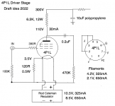
2P29Ls are low cost, so if you are in doubt, try those to begin. The transformer for B+ is not too big for these, either.
You can power the filament with a low cost EI dual-bobbin 14V 50VA transformer from your local industrial supplier and my new V9 regulators.
With these power supplies, you can experiment with 01A, 26 or 2P29L (one or two resistor changes) and hear the qualities of this wide range of tubes.
Variations on the Siberian circuit can accommodate these too, with different filament bias resistor (filament bias is excellent for all these)
Thanks Rod.. I haven’t been out of the audio loop since the pandemic and trying to get back fully this year.. I will contact you again hopefully in a few months.
I may try a 4P1L driver stage into a SE EL12n. That's an East German tube which sounds good in triode, and no top cap. Old Y8A base and mu of around 18 in triode. 18W dissipation. I'll try 4P1L and 2P29L. I have a 2P29L stage up and running so that shouldn't take long to set up. I've always 4P1L in filament bias before but I'm wondering if this would work, att.


Hi Andy,
for 4P1L, gm is nominally 6mA/V. That makes an intrinsic cathode 'resistance' of ca. 167Ω, so using an external resistor of 120Ω is a bit too high: it will reduce gm to ca. 3.5mA/V and raise ra correspondingly (bad for driving purposes).
How about using Rk of 10-12Ω, and using filament bias with 650mA filament current (parallel-connected filament-halves is the best way in all cases: lower Uf reduces the skew of bias across the filament).
The bias becomes 6.5-8V, and you can adjust Ua to get the desired anode current.
A 10-12Ω cathode resistor will keep the 4P1L performance at the optimum for driver applications.
I've made a note of your values, one version of which comes out at 6.75V bias, 10R cathode resistor, 141V on anode, 296V B+, anode resistor of 6.2K, 25mA current. Filament supply would be 15V DCHi Andy, for 4P1L, gm is nominally 6mA/V. That makes an intrinsic cathode 'resistance' of ca. 167Ω, so using an external resistor of 120Ω is a bit too high: it will reduce gm to ca. 3.5mA/V and raise ra correspondingly (bad for driving purposes). How about using Rk of 10-12Ω, and using filament bias with 650mA filament current (parallel-connected filament-halves is the best way in all cases: lower Uf reduces the skew of bias across the filament). The bias becomes 6.5-8V, and you can adjust Ua to get the desired anode current. A 10-12Ω cathode resistor will keep the 4P1L performance at the optimum for driver applications.
For practical purposes I want to use a 12V AC transformer for the filament bias supply into your reg, which would give more like 13.5V DC with some filtering, so would be looking at a maximum of 4.5V bias. That should be in the ballpark. Cathode resistor of 6.8R
Hello Bela - I've used the EL12n before for a while, and it is indeed easy to drive. I wouldn't be using a CCS on the 4P1L anode - I'd be using a resistor. I prefer the tone of acoustic instruments with a resistor or a good plate choke, and I listen to a lot of classical music and opera.
I've made all these filament bias circuits many times in past years, but these days I'm not looking for perfection, just simple solutions that sound good. I don't actually need a DHT for my own system which is various 6J5 variants into 2a3. But audio friends do want DHT stages e.g. to drive Pass F4 amps or as line stages, and it's not the kind of thing you can easily get over the counter. I have a 2P29L stage up and running so out of curiosity I thought I might revive a EL12n output stage. I'd expect the EL12n to sound inferior to the 2a3 but the 2P29L to sound better than the 6J5. Swings and roundabouts. Same with a 4P1L input stage.
I've made all these filament bias circuits many times in past years, but these days I'm not looking for perfection, just simple solutions that sound good. I don't actually need a DHT for my own system which is various 6J5 variants into 2a3. But audio friends do want DHT stages e.g. to drive Pass F4 amps or as line stages, and it's not the kind of thing you can easily get over the counter. I have a 2P29L stage up and running so out of curiosity I thought I might revive a EL12n output stage. I'd expect the EL12n to sound inferior to the 2a3 but the 2P29L to sound better than the 6J5. Swings and roundabouts. Same with a 4P1L input stage.
Andy, why not try the F2a:s I sent you last year. Should sound better than the EL12n.Hello Bela - I've used the EL12n before for a while, and it is indeed easy to drive. I wouldn't be using a CCS on the 4P1L anode - I'd be using a resistor. I prefer the tone of acoustic instruments with a resistor or a good plate choke, and I listen to a lot of classical music and opera.
I've made all these filament bias circuits many times in past years, but these days I'm not looking for perfection, just simple solutions that sound good. I don't actually need a DHT for my own system which is various 6J5 variants into 2a3. But audio friends do want DHT stages e.g. to drive Pass F4 amps or as line stages, and it's not the kind of thing you can easily get over the counter. I have a 2P29L stage up and running so out of curiosity I thought I might revive a EL12n output stage. I'd expect the EL12n to sound inferior to the 2a3 but the 2P29L to sound better than the 6J5. Swings and roundabouts. Same with a 4P1L input stage.
Hello! Indeed, a good idea but for later. This is an amp to sell, hence the EL12n. It's a good sounding tube.Andy, why not try the F2a:s I sent you last year. Should sound better than the EL12n.
Keep in mind that standard DAC output is 2V rms nominal, and is often more than that, since it makes the SNR look better.so would be looking at a maximum of 4.5V bias.
2V rms is ca. 2.84V zero-to-peak, 5.7V peak-to-peak. I think it's risky to offer a DAC-input that can't support at least 8-9V signal swings, like we do with the 26 preamps.
Thanks Rod, that's very helpful.Keep in mind that standard DAC output is 2V rms nominal, and is often more than that, since it makes the SNR look better.
2V rms is ca. 2.84V zero-to-peak, 5.7V peak-to-peak. I think it's risky to offer a DAC-input that can't support at least 8-9V signal swings, like we do with the 26 preamps.
Andy,
If you see the EL12n datasheet, the -recommended- bias is -7.5V (250V a-c, 72mA anode, 11 mA G2 current, 90R cathode resistor), so any driver tube fulfils 15Vpp swing (about 3-5x gain).
Sample:
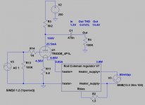
View attachment 1067128 View attachment 1067134
Hi,
what does it mean ??! 4p1l has allowable voltages of 4.2 / 2.1V
12.28V-10.14V = 2.14V
thank you !!12.28V-10.14V = 2.14V
And what then sets the bias? R11?
please tell me the formula for calculating value of the resistor?Yes.
Cathode current (which is equal to plate current, if grid current is zero) + filament current flow trough bias resistor (R11), generates -in this case- 10.14V.
This (+ about half of filament voltage) is grid voltage (cathode is more positive than grid, so it's relative negative grid voltage).
p.s.
Filament biased DHT tube "grid voltage" not equivalent to bias resistor voltage, some part of filament resistance*filament current also counts on it.
It's theoretical (as anode-cathode voltage -measured anode voltage relative to cathode "legs"- too), only measuring of anode current is the real value.
(Filament current + anode current)* bias resistorplease tell me the formula for calculating value of the resistor?
646.17mA + 30.13mA= 676.3mA
0.6763A*15Ohm=10.14V
Thanks a lot(Filament current + anode current)* bias resistor
646.17mA + 30.13mA= 676.3mA
0.6763A*15Ohm=10.14V
So, -10.14V is the bias in the case?
a bit difficult to understand. I did not find a clear explanation on Rod Coleman's site, although there is a lot of text.
ok,
then for the 4.2V filament supply, we have
325ma + 30ma = 355ma
0.355A * 15 Ohm = 5.32V
and Coleman regulator should have 5.32V + 4.2V = 9.52V
Am I right?
Last edited:
- Home
- Amplifiers
- Tubes / Valves
- 4P1L DHT Line Stage

