
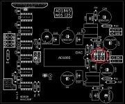

Hi, on this board the DAC chip AND the opamps share the same +-5V psu. The AD1865 analogue part needs the +-5V, so you can't just raise it to +-12V. If you want to supply the opamps with +-12V, you need to supply it separately and then you need 3 psus. You just have to remove two of the jumpers (probably J10 and J11) and apply the third supply there.
And Sparkos voltage is minimum +-6VI wasn't sure that they share 5V. Thanks.
So whoever tried Sparkos at AD1865 PCB - didn't hear how Sparkos really works ...

Last edited:
I got it.Anyone have a AD1862 chip to sell to me?
I only need 1.
5v limits the choice of OP amps.
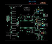
I/V opamps can be powered separately. Don't install J10, J11, J12 and J13. Use these pins for the +-12V PSU:
(+-5V still be needed for the AD1865)
Attachments
miro, i tried all of yours pcb, ad1862 with headphone amp, ad1865 v1.1,1.3 and jlsound version, would you consider to make a gpio 40 pins version for raspberry pi? i think the connection between the pi and the dac as short as possible, i tried 5, 10, 15 ,20 and 50cm flat cable and 10, 20 cm dupont cable, 5 cm ,10cm flat cable and 10cm dupont cable no different, but 50cm, the sound likea put the speaker in the toilet, very funny.......
now my connection is through "i2s to hdmi pcb" > hdmi cable > "hdmi to i2s pcb", sound beeeeeeautiful, anybody who finished the pcb, try this, no expensive but will give you suprise when the sound come out.
now my connection is through "i2s to hdmi pcb" > hdmi cable > "hdmi to i2s pcb", sound beeeeeeautiful, anybody who finished the pcb, try this, no expensive but will give you suprise when the sound come out.
We need a whole PSU2 just for opamps.Thanks miro160. Can i use +5 and -5 pins and 0 of VA? 0 common for 12V?
Then another PSU2 with + 5V / -5V for DAC
+ 5V for shifters and JLS output
And the third in my case Studer900 LPSU board for XMOS JLS (I want only D+ and D- from PC)
It's real overkill. But who cares😎
Last edited:
I assume that if the power supply of the opamp is from + -5V and higher, there will be no difference for the ears, but the measuring device can detect lower THD 🤓Miro, would you expect a noticable sq benefit.
For the best sound experience avoid direct I2S output from the rpi. Instead use the rpi USB and connect here a high quality USB-I2S device with clean clock (like jlsounds or another xmos based ... I think even the cheap PCM2706 with rpi USB will sound better as direct I2S from the rpi) 😉 ... someone in this thread tried it ...miro, i tried all of yours pcb, ad1862 with headphone amp, ad1865 v1.1,1.3 and jlsound version, would you consider to make a gpio 40 pins version for raspberry pi? i think the connection between the pi and the dac as short as possible, i tried 5, 10, 15 ,20 and 50cm flat cable and 10, 20 cm dupont cable, 5 cm ,10cm flat cable and 10cm dupont cable no different, but 50cm, the sound likea put the speaker in the toilet, very funny.......
now my connection is through "i2s to hdmi pcb" > hdmi cable > "hdmi to i2s pcb", sound beeeeeeautiful, anybody who finished the pcb, try this, no expensive but will give you suprise when the sound come out.
In the future I can create 40 pins version also for RPI, but it will be the stop-clock 🙂
Any digital source which is not operating from the same MCLK XO as the DAC is fundamentally fault.
That applies to RPi as well as USB.
The likes of Amarero or XMOS or FiFo are merely a fix.
The best solution is not to have the problem in the first place.
Patrick
That applies to RPi as well as USB.
The likes of Amarero or XMOS or FiFo are merely a fix.
The best solution is not to have the problem in the first place.
Patrick
Yes, so you have a jittery and not synchronised souce, and you clean it up with cmplicated software / firmware / hardware.
Is that a good solution ? Are there no better solutions ?
Patrick
Is that a good solution ? Are there no better solutions ?
Patrick
- Home
- Source & Line
- Digital Line Level
- DAC AD1862: Almost THT, I2S input, NOS, R-2R